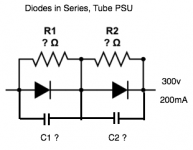
I want to use two C3D02060F SIC diodes in series in a full wave rectification for a tube preamp/amp. So 8 in total. This is because I have several. I therefore need to know what resistor values (ohm, watts) to use in parallel with each diode. I would also like to know the capacitor rating and type to use in parallel with each diode.
I've slogged through the formulae on this website:
Question about diode strings in high voltage applications - Electrical Engineering Stack Exchange
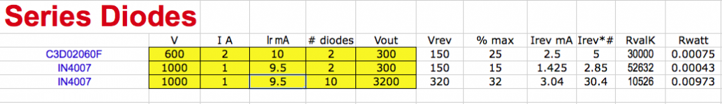
I attach my calculations. This looks correct for the case quoted (3200v, 10 diodes) but for the C3D02060F SIC diodes it looks like a resistor of 30Meg, 0.5W. this seems very large. Is this right?
Is there an easier way to find the value and wattage of each resistor used with series diodes?
And what is the correct value for 2 x C3D02060F SIC diodes in series in a rectification around 300v, 200mA for the HT.
http://www.farnell.com/datasheets/2047818.pdf
I've slogged through the formulae on this website:
Question about diode strings in high voltage applications - Electrical Engineering Stack Exchange
I attach my calculations. This looks correct for the case quoted (3200v, 10 diodes) but for the C3D02060F SIC diodes it looks like a resistor of 30Meg, 0.5W. this seems very large. Is this right?
Is there an easier way to find the value and wattage of each resistor used with series diodes?
And what is the correct value for 2 x C3D02060F SIC diodes in series in a rectification around 300v, 200mA for the HT.
http://www.farnell.com/datasheets/2047818.pdf
Attachments
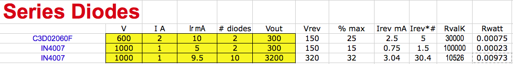
Sorry - here's a corrected calculation for the IN4007 in place of the SIC diode. Here the resistor value is 52.6Meg. Still pretty large.
Attachments
Last edited:
Can I suggest to just use a single UF4007 - that won't need any balancing parts as the PIV is sufficient for a 300V output supply.
I appreciate you may have the SiC diodes, and want to use them, and if so then I'm guessing this is for a 50 or 60Hz mains frequency power supply, in which case you won't need any balancing parts if you keep the diodes at the same temperature and allow them to keep cool, as you only need 2 in series.
I appreciate you may have the SiC diodes, and want to use them, and if so then I'm guessing this is for a 50 or 60Hz mains frequency power supply, in which case you won't need any balancing parts if you keep the diodes at the same temperature and allow them to keep cool, as you only need 2 in series.
Can I suggest to just use a single UF4007 - that won't need any balancing parts as the PIV is sufficient for a 300V output supply. I appreciate you may have the SiC diodes, and want to use them, and if so then I'm guessing this is for a 50 or 60Hz mains frequency power supply, in which case you won't need any balancing parts if you keep the diodes at the same temperature and allow them to keep cool, as you only need 2 in series.
I'd like to try both - UF4007 and the SIC diodes to see if I can hear any difference. I've read that the balancing resistors aren't essential with modern devices, but I'd still like to know the formula for calculating the resistor value since I've already spent time trying to make a calculator in Excel. A ballpark figure would save a lot of grief. Say 10meg or whatever. Also I'd like to know how to specify the capacitor in parallel with the diodes. This is a classic design and i'd like to know what the parts are.
Thanks for the advice - a real-world answer!
Lose the capacitors entirely. All they do is let noise through.
The resistors are used to force equal reverse voltage across each diode. Look in the diode specs for the maximum leakage current at reverse voltage. Then, ask your resistors to pull 3-10X that much current at your peak circuit reverse voltage. That way, even if one diode leaks twice as much current as the other, the ballast resistors dictate the circuit performance by dominating the leakage.
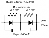
Wattage of course dependent on voltage*current at ~50% duty cycle. Metal oxides are great for this application.
The resistors are used to force equal reverse voltage across each diode. Look in the diode specs for the maximum leakage current at reverse voltage. Then, ask your resistors to pull 3-10X that much current at your peak circuit reverse voltage. That way, even if one diode leaks twice as much current as the other, the ballast resistors dictate the circuit performance by dominating the leakage.
Wattage of course dependent on voltage*current at ~50% duty cycle. Metal oxides are great for this application.
Attachments
Last edited:
Lose the capacitors entirely. All they do is let noise through. The resistors are used to force equal reverse voltage across each diode. Look in the diode specs for the maximum leakage current at reverse voltage. Then, ask your resistors to pull 3-10X that much current at your peak circuit reverse voltage. That way, even if one diode leaks twice as much current as the other, the ballast resistors dictate the circuit performance by dominating the leakage. Wattage of course dependent on voltage*current at ~50% duty cycle. Metal oxides are great for this application.
So for the SIC diode specified the leakage current is around 10mA. Let's multiply that by 5, = 50mA. If the voltage is 300v each resistor sees 150v so the calculation would be R=V/I so 3K at 7.5W. that doesn't sound right to me - where am I going wrong?
Another question - if I used a single 1200v SIC diode what's the optimum reverse current rating, larger or smaller? What's best out of these three for typical Ir?
25°..... Cree 10uA, Ween 2uA, STC 1uA
175°... Cree 40uA, Ween 80uA, STC 6uA
25°..... Cree 10uA, Ween 2uA, STC 1uA
175°... Cree 40uA, Ween 80uA, STC 6uA
Andy, I did extensive listenig to all kind of SS diodes before I switches to tube rectification. ,y favoirite have been the hexfreds for HV and germanium diodes for LV. ideally used not as a bridge, but two way with CT...each diodes adds noise. so three in series are adding each others noise...normally when current rating goes up, recovery time goes up as well...just my 5ct.
All things being equal lower reverse current is always better. Here the STC looks like the winner if the specification can be believed.
IMO stacking diodes in series should be avoided when possible, and then after that choose the diode that would allow for the smallest number of stacked diodes and the lowest reverse leakage current.
I think in one of your earlier examples you may have confused mA and uA.
Choice of resistor is important. I would recommend carbon or metal oxide types for shunting. The capacitors were used to swamp reverse biased junction capacitance and will let HF noise through, as long as the junction capacitance is low they can probably be safely omitted.
Additional series diodes and their parallel resistors tend to reduce long term reliability IME so if there is a suitable high voltage part use that instead.
If the voltage is 300v each resistor sees 150v so the calculation would be R=V/I so 3K at 7.5W. that doesn't sound right to me - where am I going wrong?
Not wrong. 10mA is a healthy amount of reverse current. Are you sure they leak that much? Maybe 10uA not 10mA?
If you select a diode with leakage greater than 20 uA at full reverse voltage, pick a different diode.
A typical resistor would be 1 Meg at 1/2W. Sometimes, in tube power supplies your resistor voltage rating is the limitation rather than watt dissipation. Hence the suggestion for metal oxide; they handle voltage better than many other types (and are cheap).
But yes, if you can get away with one diode rather than 2 in series, one is better.
Just capacitors alone are not good for snubbing diode noise. They will store energy and then release it back into circuit. A series resistor is needed to dissipate spike energy.
That's why tube rectifiers are better, even with their problems. No worries about reverse spikes and noise. Soft start as a bonus.
That's why tube rectifiers are better, even with their problems. No worries about reverse spikes and noise. Soft start as a bonus.
Last edited:
Perhaps best to present a schematic with the power supply circuit and transformer voltages proposed, as '300V' can be applied to a few aspects.
For high frequency rectification, requiring multiple diodes connected in series, then this link indicates the issues that need to be managed, and some ballpark equations/calculations. None of those issues apply for mains frequency power supplies of typical valve equipment voltage rating and lowish load current.
https://www.stmicroelectronics.com.cn/content/ccc/resource/technical/document/application_note/d7/e9/fb/52/25/60/4f/bf/CD00003869.pdf/files/CD00003869.pdf/jcr:content/translations/en.CD00003869.pdf
Some discussion on PIV and series diode connection, and SiC use, is in first 3 sections in this link:
https://www.dalmura.com.au/static/Power%20supply%20issues%20for%20tube%20amps.pdf
Last edited:
When used in HV PSs the physical size of a resister matters so far as voltage from end to end, a factor unrelated to the power dissipated. So a 1/2 Watt resister might be stressed where a 2 Watt would be OK, even when the dissipation is not a problem
Volts per millimeter, the Electric Field Intensity matters when we get to KV & up supplies. And a CC resister would react differently than other construction.
Some resisters are more effected in terms of change of resistance per volt. All the factors that don't matter much at low voltage.🙂
Volts per millimeter, the Electric Field Intensity matters when we get to KV & up supplies. And a CC resister would react differently than other construction.
Some resisters are more effected in terms of change of resistance per volt. All the factors that don't matter much at low voltage.🙂
Switching noise can be a problem, even with tube rectifiers. As the tube goes out of conduction the leakage reactance & stray capacity of the winding in many cases results in a decaying transient. The cure is often a simple RC network across the transformer winding.🙂
SS rectifiers probably won't cure such a problem.
SS rectifiers probably won't cure such a problem.
- Home
- Amplifiers
- Tubes / Valves
- Series diodes for tube rectification - formulae?