Someone else posted, then deleted it... but I'll say something similar: I think you need to somehow get your ESP32 to emit a 32 bit stream, looks like you're outputting a 16 bit stream.
Pretty sure I'm sending 44.1khz, 32bit to the ma12070p (see the S32_LE part):
Code:# cat /proc/asound/card0/pcm0p/sub0/hw_params access: MMAP_INTERLEAVED format: S32_LE subformat: STD channels: 2 rate: 44100 (44100/1) period_size: 220 buffer_size: 440
That's what the Linux merus-amp driver sets up automatically. (Though I'm not sure why they set it to 44.1khz, the hardware supports higher sampling rates. This implies playing music with a higher sample rate will be downsampled.)
But - when I was first testing, and using the a generic I2S driver, which by default seems to assume the hardware will play multiple bit formats, it was only silence when trying to play 16-bit files. I have several files with different sample rates and bit sizes. The ma12070p would only play 32 bit files. And now that I'm using the merus driver, it's only allowing 32 bit (trying to play a 16-bit file will result in an error).
That's another avenue you can explore, get (or generate) some test files with different sample rates and bit formats. But I think you first have to coerce the ESP32 to output 32-bit PCM.
(On Linux, I actually don't have to worry about the format of the source audio, as the software will convert it to what the hardware wants on the fly.)
I hope that's not true, 'cause 16 bits is the max Squeezelite-ESP32 can send.
I was able to resample the stream to 96000. Now when I press play I get silence instead of static

I hoped my problem was with 44100, because it generated
SCLK: 1411199.625000 and that is not an acceptable CLK for 44.1kHz
44.1kHz
64 x fs = 2822.4kHz
128 x fs = 5644.8kHz
256 x fs = 11289.6kHz
512 x fs = 22579.2kHz
After changing it to 96000, got
SCLK: 3071999.500000 which is a valid CLK frequency for 96kHz
96kHz
32 x fs = 3072kHz
64 x fs = 6144kHz
128 x fs = 12288kHz
256 x fs = 24576kHz
I think the reason your 44100 files work is because you can do 32 bits.
44100 * 32 * 2 = 2,822,400, and 2822.4kHz is a valid 44100 CLK frequency.
Anyway, I'm trying to get all the volume registers set correctly, as I hope the silence is a result of the volume settings.
Sucks not having a GUI like alsamixer for the Pi.
Thanks for dealing with all my rambling.
Mike
You don't have to resample the stream actually. The only thing you have to do is to set the I2S hardware into 32-bit operation.
Afterwards you have to convert your 16-bit sample buffer into a 32-bit one.
That's rather easy.. e.g.
//example 16-bit sample value
short sample16_b = 12345;
int sample32_b = ((int)sample_16b)<<16;
Then you can write the 32-bit int buffer with the i2s_write function. Please also take care that you double the amount of bytes to write as you have now in fact twice the data load
About which pin are you talking?
The namings of the pins are a little bit weird.
There is a pin called CLKM/S (Pin 31), which must be pulled low constantly. Don't know what's the sense behind this.
Your actual MCLk input is PIN 32 -> and this can be connected together with Pin21.
I also had some problems with cracking sound at the beginning.
I tried to connect the MA12070P to an ADAU1701. And it just didn't work. But then I found out finally that the ADAU1701 pulls the IO pins only to approx 0.6V low-voltage level which doesn't seem to be enough for the Merus-AMP to recognize a stable 0-level.
I tried then an STM32 to connect to the I2S interface and this worked without any further problems.
Can you maybe check the voltage high/low levels on the I2S bus? Maybe it works with an additional level shifter.
Which evalboard are u using by the way? I have the big-one with the USB-I2C bridge. There is a nice software-tool from infineon where you can try out all the I2C settings inside the computer. There is even live-level monitoring and a digital signal limiter integrated.
The same problem for me!
By the way:
I'm already thinking since a little bit longer time to make a further hobbyproject with that MA12070P.
I recently managed on the ESP32 to get the I2S running bidirectionally.
I had in my mind something with 2* MA12070P, one ESP32 or so and then you can run DSP stuff on the ESP32 (e.g. IIR-filter) and manage a full 2.1 active controlled speaker system with WiFi-Control.
But not 100% sure yet about the details.
Anyone up for a collaboration?
I join you! In fact i was thinkig the same idea. Also I would like to add usb support to use as usb - i2s converter with esp32, does anyone know if this is possible ?
For my own project I will personally use 2(3) my boards with MA12070P and then connect them to ADAU1452, I think it's esier to implement FIR filter by user in Sigma Studio and add digital volume control like this ADAU1452 for Digital Volume control - Q&A - SigmaDSP Processors and SigmaStudio Development Tool - EngineerZone
Very interesting, since adau1701 should have the same pin architecture, but this does not work because the 0.6v low level does not match with ma12070p.
I just got the SMSL SA300 for listening impressions of the MA12070 chip. The amp sounds very nice - listening to them with both RCA in and BT input. Both were excellent with no audible noise even with ear pressed to speaker cone. At about 8w into 10ohms, it’s pretty clean at 0.007% THD. Noise floor is extremely low - quite impressive actually.

Attachments
ok, si this is my history. I buy two ma12070 from lusya store in aliexpress. They send me the wrond model, so I receive the ma12070p. For documentation reason I share with you guys picture of my board. I remove the capacitors from the imput and make just jumpers. The following resistors are placed R7, R4, R5, R6. These ones are not soldered R3, R2, R1.
Also I solder SD1 pin with SCK. I try to use adau1701 chip with the board 3e audio, but this produce noise, mainly because the low level of adau1701 become 0.6v and this is not recognized by ma12070p as low level. Also I test with qcc5125 bluetooth module. This has i2s output also, but the sound in speaker is noise with some music.
I use a meanwell power supply with 24v 350w.
Nest step with raspberry pi...
Last edited:
XRK,
How does this amp sound when compared to the TDA 7293 board ?
They both sound very good and hard to say which is better. I think the TD7293 has the advantage if you are planning on running them with lower sensitivity speakers or in a larger room where you need 25w+, at which point, the MA12070 runs out of steam and the distortion rises dramatically. The TDA7293 on the other hand, is a 100w amp (if given the right supply voltages) and 25w is just another moderate operating point with low distortion.
I do think that the MA12070 does an admirable job though in the 8w to 15w range. Nice deep powerful bass extension and very clear mids and highs.
For example, here is 10w range from TD7293 Xmax by Jhofland - 0.001% THD and 2nd and 3rd harmonic are about even for a pleasing sound signature:
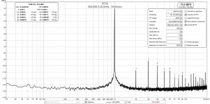
Vs circa 9w from MA12070 (as seen above but placed here for easy comparison) - about 10x more THD and higher 3rd order than 2nd order so will sound like it has a bit more "bite":
Last edited:
I could make work the ma12070p with qcc5125 and an Arduino with initialization code to configure the correct i2s format. However, my code is not complete. At power up, I follow the start up sequence of ma12070 but without clk present because the Bluetooth module start up later, and this does not clock the signal bclk if there is not music playing. So I force the sequence by restarting the ma12070p and its code sequence meanwhile music is playing and now bclk is present. But this demand playing music to configure the ma12070p.
So my question is, how you guys handle the clck before enable the amp.
I am planing to read bclk in the Arduino to check the clocking signal present to start the config sequence for the amp. If there is no bclk signal I will keep disable the amp
So my question is, how you guys handle the clck before enable the amp.
I am planing to read bclk in the Arduino to check the clocking signal present to start the config sequence for the amp. If there is no bclk signal I will keep disable the amp
Last edited:
So my question is, how you guys handle the clck before enable the amp.
p
Well the thing is, that the way, how you implemented it, is a little bit unusual.
Normally, those Audio-bluetooth modules are complete SoCs with integrated microcontrollers.
As I guess that you don't have access to the SDK from qualcomm, this device is more or less a black box for you only.
But I definitely know that those Qualcomm Bluetooth-modules have an integrated I2C master to initiate e.g. the amplifier configuration.
In normal professional-grade developed consumer devices, this is also the way to go usually. At first the I²S interface in the host is started (don't matter if bluetooth is connected already or not). Then doing the I²C configuration to the amp and you're usually sending out empty-samples until you got your first valid bluetooth-connection with audio-signals.
But as I said, things like this are only manageable if you have access to the SDK tools and documentation of the manufacturers. Most of the times this is only distributed via NDA or in some cases you can only get the design by cooperation with some dedicated preferred design-houses of the silicon manufacturers.
Same thing with the Zhuhai Ji-lie Bluetooth-devices on eBay.
I you don't want to use that arduino co-solution I would recommend you to switch over to another chip where code examples and SDK are public available, e.g. ESP32 or if you want a little bit more professional solution go e.g. for CYW20721.
Thank you very much for your answer. As you said I don't have sdk of qcc5125.
However, I could elaborate a solution. The same arduino (MSP430 with arduino framework) that is configuring the amp is checking lrck in a input to find changes and start a sequence of configuration. Also, it checks if the lrck is idle in order to disable the amp with its correct sequence.
I have enough flash in the microcontroller to program a lcd in order to show the status of the amp. So I will add this feature later.
I am thinking to add a tristate buffer with muxer to add two more sources. A eps32 for wifi streaming audio, and a XU208 usb to i2s.
But for the moment i will keep my bluetooth module that also has usb input and i can use as usb dac.
I am planning to add a second amp and configure as one output mode. So at the end I hope to make the same config as an user here with two amp for each channel.
Last edited:
Thanks for all the information everyone! I got interested in the AliExpress boards and recently ordered one of the analog boards and one of the digital boards. While waiting for the boards to arrive I’ve read the datasheets, the Infineon documentation for their evaluation boards and this thread. I do have a couple of questions bugging me:
Digital board (MA12070P): I noticed the AliExpress board doesn’t have a MCLK line on the I2S connector. Does this board connect the SCK input to the MA12070P CLK pin in addition to routing it to the IN0A pin? I would hope so since they left off MCLK.
Analog board (MA12070): The board defaults to 20 dB gain with an option to program it to 26 dB. I understand the procedure to program it to 26 dB, but will the change have to be repeated every time power is cycled? The data sheet calls this “mode default overwrite” so I’m hoping the change will stick (glass half full).
And a question to jealcuna (post #388): Why did you jumper SCK to SD1? In two channel BTL mode the documentation shows that SD1 (unused) should be grounded. Did I miss something?
Sigh.... I did a little more digging and think I answered both my Digital board and @jealcuna questions. It appears that the AliExpress board uses the (unused in 2 channel mode) SD1 line as the MCLK input which is routed to the CLK pin.
Last edited:
Yes it is, also you can search the schematic of the evaluation board which is technically the same of the AliExpress board.

I'm trying to figure out how to turn off the MA12070 board from Audiophonics. I know there is a En (enable) pin on the board, but as far as I could figure out, I need to connect this pin to +6v in order to make the amp go into standby mode, but there is no such output on the board. Another solution was to connect mute to gnd, however this doesn't lower the current consumption of the board to an acceptable level.
The other solution I thought of, was just to have the amp boards (i'm planning on using 2) connected to a push switch. I'm however unnsure whether the switches can handle the inrush current of the boards. This might be the best solution?
Does anyone have input on the matter? 🙂
This is for a battery powered system, so efficiency is highly prioritized, making relays a unwanted solution because of high energy consumption.
You can use a tricky and not well-made solution. You can take 5v from the big mlcc capacitor near to ic regulator. then use a switch or something to disable the amp. If you made some configuration with i2c com, you will lose this.

Finally finish my amp configuration with 2 ma12070p taobao boards, a qcc5125 bluetooth LDAC and an arduino to config the amps. Each amp handle a channel. I will post more information later. I am very happy with the sound quality.  😀😀😀
😀😀😀
😀😀😀hello guys. i read the posts on this thread and i buy a board MA12070 from Audiophonics - Produits Hi-Fi Audio Electroniques et DIY - Audiophonics, now waiting to come. One request from you, users of ma120xxx is to post the code (.ino file) with handlers of i2c, features volume +/-, UN/enable, UN/mute.
- Home
- Amplifiers
- Class D
- Infineon MA12070 Class D