Consider me one of those people who knows just enough to get himself in trouble 🙂
That being said I have a Sherbourn 2 channel amp that has died and I would like to salvage some of the parts for it.
As most do you know Sherborn has been bought and sold twice so getting support or finding technical manuals or schematics is nearly impossible (unless one of you wonderful people happen to have access to them)
After disassembling this amp and testing through as much as I am capable of I believe that the toroid‘s/ The bridge rectifiers and all of the power supplying the two amplifiers that are within this chassis are all good, and that the failure is somewhere in the input circuitry or the control circuitry that controlled the outputs of this amplifier (all of that I don’t need, I would replace with new circuitry)
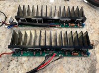
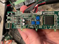
Attached are photos of the two mono amp modules that were contained within this chassis to create the two channel amp, I have identified that the power in is 57 V DC, however I can’t make heads or tails of what one of the two smaller ribbon cables would have been the signal in nor what that signal should be.
I would appreciate any advice to this noob as I have always wanted to hack into an amplifier and make it my own.
That being said I have a Sherbourn 2 channel amp that has died and I would like to salvage some of the parts for it.
As most do you know Sherborn has been bought and sold twice so getting support or finding technical manuals or schematics is nearly impossible (unless one of you wonderful people happen to have access to them)
After disassembling this amp and testing through as much as I am capable of I believe that the toroid‘s/ The bridge rectifiers and all of the power supplying the two amplifiers that are within this chassis are all good, and that the failure is somewhere in the input circuitry or the control circuitry that controlled the outputs of this amplifier (all of that I don’t need, I would replace with new circuitry)
Attached are photos of the two mono amp modules that were contained within this chassis to create the two channel amp, I have identified that the power in is 57 V DC, however I can’t make heads or tails of what one of the two smaller ribbon cables would have been the signal in nor what that signal should be.
I would appreciate any advice to this noob as I have always wanted to hack into an amplifier and make it my own.
Attachments
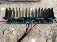
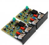
My take on what I can see is that you have a single output stage only there. 6 NPN power transistors (so a 'Quasi Complementary output) and with three smaller transistors bolted to the heatsink which are probably used as diodes for thermal compensation.
I would imagine the power supply is a split type (- and + type for example +50v and -50v).
None of the driver stages and front end appear to be present on the board.
I would imagine the power supply is a split type (- and + type for example +50v and -50v).
None of the driver stages and front end appear to be present on the board.
Correct that’s only one of the amplifier sections, there is a twin that sat directly next to it in the chassis.
Before even ask any additional questions, Is that architecture some thing I should even be building onto? My hope is that this will be able to drive my new to me towers that I just acquired and by saving some money on the amplifier early will allow me to spend a little more on my source/ pre now and invest in amplification down the road.
Before even ask any additional questions, Is that architecture some thing I should even be building onto? My hope is that this will be able to drive my new to me towers that I just acquired and by saving some money on the amplifier early will allow me to spend a little more on my source/ pre now and invest in amplification down the road.
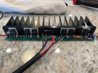
Here are a couple photos of the power stage from that amp, what got me interested in fixing this is that it seemed to be built as if it was a dual mono chassis with separate toroid’s separate bridge rectifiers separate amplifier sections etc. and I thought this could potentially make for a good 2ch starter amp.
Attachments

I like the heatsinks they look quality .
What you should post are the identity of the output devices --- BJT/Mosfet ? -numbering .
What you need now is to build /design an input/VAS stage / bias /driver stage to suite the output devices unless those smaller BJT,s are drivers ?
What you should post are the identity of the output devices --- BJT/Mosfet ? -numbering .
What you need now is to build /design an input/VAS stage / bias /driver stage to suite the output devices unless those smaller BJT,s are drivers ?
It is difficult to advise really, and particularly so just from pictures. Are the toroids identical for example. If not then one may be for the front end section and one for the power stages.
If the voltages are +57 and -57 then that is pretty high and possibly limits what you build... and so much depends on what you are able to do yourself.
Retaining those output modules as they stand limits your choice to a Quasi design (all NPN outputs) and you also have to identify all the connections and then there are problems of connecting high power wide bandwidth output stages via leads to the front end circuitry.
You are down to designing your own boards for any front end circuitry... its no easy task... I think even an experienced designer would think twice about trying to repurpose the existing circuitry.
Sorry its not more hopeful 🙁
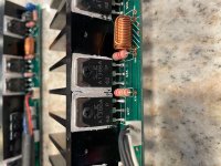
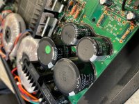
Actually I think I'm wrong on the Quasi... I saw a '3' on the right hand devices. Can't get a clear image but does it start 'Axxx'.
The left hand ones are 2SC351 9??? is it.
The left hand ones are 2SC351 9??? is it.
Just a crazy thought before I sign off...
What about some Quad 405 boards. They should just about be OK voltage wise I would have thought and should be able to be clamped to the existing heatsinks. The 405 ran on nominal -/+50 volt rails.
There are lots available if you look. It was just an idea.
What about some Quad 405 boards. They should just about be OK voltage wise I would have thought and should be able to be clamped to the existing heatsinks. The 405 ran on nominal -/+50 volt rails.
There are lots available if you look. It was just an idea.
Attachments
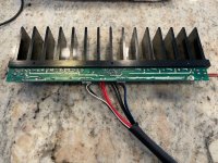
Attached is a close photo of the part, In the second photo is the includes both amp modules.
Not Quasi 🙂 Its a complementary output stage with NPN and PNP devices. The 2SA's are the PNP's.
It doesn't really change how difficult a project it would be though.
I really wish Emotvia would not be so stingy with the repair docs so I could just fix this as it sits.
As far as I can tell it’s just one very burnt resistor on the board that I can’t identify (from being so burnt) lol. I’m sure something else could’ve led to its demise but I would at least need to know what it is to chase down the problem.
As far as I can tell it’s just one very burnt resistor on the board that I can’t identify (from being so burnt) lol. I’m sure something else could’ve led to its demise but I would at least need to know what it is to chase down the problem.
It is difficult to advise really, and particularly so just from pictures. Are the toroids identical for example. If not then one may be for the front end section and one for the power stages.
If the voltages are +57 and -57 then that is pretty high and possibly limits what you build... and so much depends on what you are able to do yourself.
Retaining those output modules as they stand limits your choice to a Quasi design (all NPN outputs) and you also have to identify all the connections and then there are problems of connecting high power wide bandwidth output stages via leads to the front end circuitry.
You are down to designing your own boards for any front end circuitry... its no easy task... I think even an experienced designer would think twice about trying to repurpose the existing circuitry.
Sorry its not more hopeful 🙁
Yes the toroids are twins and so is every down stream component until it gets to the amp boards. Oh well I guess I will just shove some Icepower amps in the chassis and see what happens


Not bad quality components and the board is good quality its a pity you cant replace the burnt out resistor or at least make a judgement on its value .
Its no big deal taking your time and checking the active and non active components to narrow down this fault .
Its no big deal taking your time and checking the active and non active components to narrow down this fault .
I had not thought about it being positive and negative voltage..... so yes pin to pin it was 57ish volts, but when I reference them from ground it’s -28.3 and +28.3.It is difficult to advise really, and particularly so just from pictures. Are the toroids identical for example. If not then one may be for the front end section and one for the power stages.
If the voltages are +57 and -57 then that is pretty high and possibly limits what you build... and so much depends on what you are able to do yourself.
Retaining those output modules as they stand limits your choice to a Quasi design (all NPN outputs) and you also have to identify all the connections and then there are problems of connecting high power wide bandwidth output stages via leads to the front end circuitry.
You are down to designing your own boards for any front end circuitry... its no easy task... I think even an experienced designer would think twice about trying to repurpose the existing circuitry.
Sorry its not more hopeful 🙁
Great catch!
Does that make this better or worse? 🙂
Not bad quality components and the board is good quality its a pity you cant replace the burnt out resistor or at least make a judgement on its value .
Its no big deal taking your time and checking the active and non active components to narrow down this fault .
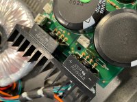
I can identify the signal path up to that burnt resistor and the couple of parts after that, but it’s feeding a ribbon cable that goes to another smaller board or all the componentry gets much smaller and I have no idea what item on sideboard to use to reference what the voltage should be so I can’t figure out what that resistors value should be.
We are at 15VDC before it. And there are only a couple capacitors Alpha direct for it heads to that daughterboard.... from there it’s beyond me
It supply’s the red (#1) on that 7 pin ribbon, and I can’t see a device immediately that has a voltage value sub 15 V DC to reference.
Thoughts?
Attachments
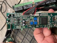
If there is only one such resistor it is unlikely to be associated with the power amplifiers. It may be for the control and protection circuitry relays etc., possibly even a low voltage supply dropping resistor for the preamps. Conversely, if its part of an amplifier it will have a twin somewhere - try checking the part numbers and clues like resistor number R001 in the left channel is equivalent to R101 in the right. That's a convenient and very common manual parts numbering scheme but not easy with design software and auto parts numbering protocols.
Having found a similar part in the other channel isn't the end if it though, you have to track down the reason the first one burnt. At least though, you would have the good/bad circuit voltages to track down the area.
Having found a similar part in the other channel isn't the end if it though, you have to track down the reason the first one burnt. At least though, you would have the good/bad circuit voltages to track down the area.
I had not thought about it being positive and negative voltage..... so yes pin to pin it was 57ish volts, but when I reference them from ground it’s -28.3 and +28.3.
Great catch!
Does that make this better or worse? 🙂
It gives you much more choice. It would be great for an LM3886 (chip) based output stage..
- Home
- Amplifiers
- Solid State
- Need a push in the right direction