This is in response to folks challenging the premiss I presented claiming turning on a high power amp at the zero crossing will result in less inrush current. A couple forumites pointed out Douglass Self and some other prominent audio types claimed that a zero cross start results in more inrush current not less due to the back EMF being generated slower thus increasing the current quicker. (?)
I constructed an assembly that simply interrupts the neutral line of a power cord and inserts a 0.1ohm resistor in series. I used my dual channel Tektronix to record waveforms during start up. See the attached photos. The jig uses a terminal block a current sense R and the two scope probes.
The best way to set up the scope is to not count on the neutral being at GND potential but rather attach ch1 probe to one side of the R and ch2 probe to the other side, then set ch2 on invert and select "add ch1 to ch2". What's interesting is I initially tried interrupting the hot line with the sense R. This didn't work well because I assume the scopes common mode rejection goes to hell the higher the V is away from it's third prong ground as I witnessed a constant 60hz sign wave of small amplitude even with no current being drawn. On the other hand interrupting the neutral worked really well with no sign of 60hz with no current being drawn.
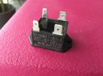
The amp I'm using is a Peavey CS800, 400W/ch comercial stereo amp with huge transformer and filter caps producing +/-80Vdc. The unit weighs 53lbs most of which is the massive transformer (8"x6"x6"). As designed it uses a triac to pass the input AC which is primarily there to protect the power switch as only the triac firing current goes through the switch. But......I maintain there's a secondary benefit - reduced inrush which several forumites challenged.
Capturing the turn on event when a zero cross occurs with a triac is easy as it will only turn on at a zero cross. Capturing without - not soe easy as I had replaced the triac with a jumper wire. I simply plugged in the power cord, asynchronously with the 60hz of course, to generate waveforms on the scope. I performed many turn-ons and recorded the waveform on the scope snapping a shot of the screen with my phone so that I could catch possibly the worse case.
All of this lined up with what i expected to see.
Observations:
1. The current is drawn as soon as the V overcomes the forward voltage required to turn on the rectifier diodes to charge the caps.
2. The voltage across the R, and thus the current decays as the caps charge up in light of this.
3. It was random whether the first peak would be a negative or positive pulse in both cases with and without triac.
Results:
Without triac, the worse case I got with five turn-on tries was about a 10v first peak across the 0.1ohm which equals 100amps (wow) Some were less as is expected. Keep in mind I may not have plugged it in exactly at the peak V so 10v may not be the worse case. See the attachment.
With triac, the first peak was always the same amplitude, ie 8 volts. the only difference would be whether it was negative or positive swinging as expected. This equates to 80 amps. (wow too) not much better but certainly less and not more reported by other folks.
Really this is still a lot of inrush current and I applaud the efforts to tame it with soft starts. I just wanted to dispel a theory about triac start up. The triac I used is the following - STMicroelectronics BTA40-800B $10.00 at Digikey.
I constructed an assembly that simply interrupts the neutral line of a power cord and inserts a 0.1ohm resistor in series. I used my dual channel Tektronix to record waveforms during start up. See the attached photos. The jig uses a terminal block a current sense R and the two scope probes.
The best way to set up the scope is to not count on the neutral being at GND potential but rather attach ch1 probe to one side of the R and ch2 probe to the other side, then set ch2 on invert and select "add ch1 to ch2". What's interesting is I initially tried interrupting the hot line with the sense R. This didn't work well because I assume the scopes common mode rejection goes to hell the higher the V is away from it's third prong ground as I witnessed a constant 60hz sign wave of small amplitude even with no current being drawn. On the other hand interrupting the neutral worked really well with no sign of 60hz with no current being drawn.
The amp I'm using is a Peavey CS800, 400W/ch comercial stereo amp with huge transformer and filter caps producing +/-80Vdc. The unit weighs 53lbs most of which is the massive transformer (8"x6"x6"). As designed it uses a triac to pass the input AC which is primarily there to protect the power switch as only the triac firing current goes through the switch. But......I maintain there's a secondary benefit - reduced inrush which several forumites challenged.
Capturing the turn on event when a zero cross occurs with a triac is easy as it will only turn on at a zero cross. Capturing without - not soe easy as I had replaced the triac with a jumper wire. I simply plugged in the power cord, asynchronously with the 60hz of course, to generate waveforms on the scope. I performed many turn-ons and recorded the waveform on the scope snapping a shot of the screen with my phone so that I could catch possibly the worse case.
All of this lined up with what i expected to see.
Observations:
1. The current is drawn as soon as the V overcomes the forward voltage required to turn on the rectifier diodes to charge the caps.
2. The voltage across the R, and thus the current decays as the caps charge up in light of this.
3. It was random whether the first peak would be a negative or positive pulse in both cases with and without triac.
Results:
Without triac, the worse case I got with five turn-on tries was about a 10v first peak across the 0.1ohm which equals 100amps (wow) Some were less as is expected. Keep in mind I may not have plugged it in exactly at the peak V so 10v may not be the worse case. See the attachment.
With triac, the first peak was always the same amplitude, ie 8 volts. the only difference would be whether it was negative or positive swinging as expected. This equates to 80 amps. (wow too) not much better but certainly less and not more reported by other folks.
Really this is still a lot of inrush current and I applaud the efforts to tame it with soft starts. I just wanted to dispel a theory about triac start up. The triac I used is the following - STMicroelectronics BTA40-800B $10.00 at Digikey.
Attachments
You have to measure the current in the primary, you cannot see the magnetizing current in the secondary, but you need an isolation transformer or clamp ammeter for this.
If the current runs through you or your measuring equipment not much will be left
If the current runs through you or your measuring equipment not much will be left
Too bad that you did not show the AC waveform along with the current waveform to show the inrush current vs voltage at turn on.
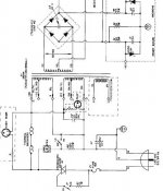
I am measuring the primary current. See the attached schematic of the AC input. I have the sense resistor in series with the neutral on the power cord.
I would need more than a two channel scope to measure the AC waveform at turn-on. I don't have such. Using a differential probe would free up a channel I suppose. Without one, inverting a channel and adding it to the other is all I can do.
I would need more than a two channel scope to measure the AC waveform at turn-on. I don't have such. Using a differential probe would free up a channel I suppose. Without one, inverting a channel and adding it to the other is all I can do.
Attachments
Bansuri, if your point is that the secondary current is greater when starting at zero cross, that's something i did not measure. I suppose another experiment might conclude this.
This is in response to folks challenging the premiss I presented claiming turning on a high power amp at the zero crossing will result in less inrush current.
Who claimed this? Zero Voltage Switching (ZVS) is easy and works well for capacitive loads (like in SMPSs). ZVS is not suitable for inductive loads like transformers and motors, in fact it could happen that when zero voltage occurs, the current is at a maximum, so the switch has to hold the maximum voltage and the maximum current. Zero Current Switching (ZCS) is the way to go for such loads, but it is more difficult to implement, since it requires real time measurement of the power factor, in order to determine the phase shift between the voltage and the current.
But for limiting the inrush current for a big power transformer there is little reason to bother with either; a power resistor shunted (after a short delay) by appropriate relay contacts is all what's needed.
I think I get your point syn08 but I believe you are talking about those cycles that occur beyond the first cycle. Before the first cycle there is no voltage and no current correct? 0x0 = 0
The simple low resistance of the transformer winding dominates for that first cycle and as illustrated in those scope images the current will be lower for that first cycle if you connect at the zero cross than at any other point.
I'm not trying to protect a triac with 1000amp pulse withstanding spec and a continuous current rating of 40A. I'm trying to lower the first cycle of inrush current to protect the transformer/wiring and to keep the input fuse fast enough and low enough it will blow during some potentially destructive event before expensive active components do. The zero cross start can lower the value of the main fuse by 20% I estimate.
Yes, soft start circuits using relays and resistors are a more aggressive approach with a wider margin of protection. I don't think I'd use a conventional relay though. I've fixed a few amps with pitted start relay contacts. I think an SCR bypassing an NTC resistor on the order of 10ohms cold would be the ultimate. ~ $60.00 and your labor.
But.....for $10.00 and 10 minutes of install time (very simple mounts to the floor with two holes) I'll take the 20% reduction in inrush and the protection it offers the power switch contacts that the particular triac offers.
Dangerous stuff. Let's hope other people won't try to replicate your experiment, especially in Europe (in the region of Brussels, where I live, both wires are live because the system is 230V between phases)I constructed an assembly that simply interrupts the neutral line of a power cord and inserts a 0.1ohm resistor in series. I used my dual channel Tektronix to record waveforms during start up. See the attached photos. The jig uses a terminal block a current sense R and the two scope probes.
The best way to set up the scope is to not count on the neutral being at GND potential but rather attach ch1 probe to one side of the R and ch2 probe to the other side, then set ch2 on invert and select "add ch1 to ch2". What's interesting is I initially tried interrupting the hot line with the sense........
.Where did you get this from?Capturing the turn on event when a zero cross occurs with a triac is easy as it will only turn on at a zero cross
A triac turns on as soon as the conditions (Igt, Vt1-Vt2, Ih) are right.
It will however always turn off at current zero crossings
Some general observations: for a purely inductive load, peak voltage switching is advantageous.
For a purely capacitive load, ZVS is best, but real world loads tend to be somewhere in-between, and the optimum lies at an intermediary angle difficult to determine without experimentations or simulations
That may be true when you do it repetitively (every cycle), such as in a light dimmer. You are advocating for the minimum current point, which is 90 degrees off. Yes, you are correct that the current is either leading or lagging the voltage. But that's not what we're talking about here.
He's talking about the first cycle only. At t=0, both voltage and current are zero. Doesn't matter if the load impedance is inductive or capacitive, the current HAS to be zero.
And the instantaneous current at the switch point is not relevant here. He's trying to minimize the amplitude of the first cycle of current.
I believe the OP has made a good point and defended it successfully.
If you have a thermal fuse in direct contact with the limiting resistor, you have a fail safe system if your relay control or contacts have issues.But for limiting the inrush current for a big power transformer there is little reason to bother with either; a power resistor shunted (after a short delay) by appropriate relay contacts is all what's needed.
I've fixed a few amps with pitted start relay contacts. I think an SCR bypassing an NTC resistor on the order of 10ohms cold would be the ultimate.
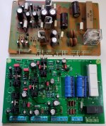
This is what I use, I do not like those NTC's or any resistor cooking away under a fault condition.
Digi-key
317-1130-ND SDF DF104S
A131149-ND SQBW203R3J You have to take the chassis mount bracket off for mounting to a pcb
255-2373-ND ALE1PB48
Attachments
Last edited:
You can easily measure the primary inrush without anything attached to the secondary and then compare it with the current with load.
The magnetizing current without load will still be quite high, but is 90° shifted in phase. It is bigger in the first cycle depending on the pre magnetization of the Xformer core. When it has reached the steady value it is stable and not depending on the load.
Luckily it is not measured by the counter because of the phase shift.
Last edited:
I just set it up again to check my premise that the triac always turns on close to the zero crossing. This time I monitored the AC on the load side of the triac, put the scope on single sweep and observed the waveform.
I was wrong. It's variable when in the cycle the waveform commences which makes sense now that I think about it. So I retract almost everything I said.
There is some other reason the first cycle of current draw is reduced though. Along those lines I did notice that the peak voltage that was reached was 20% less on the first cycle than the rest of the cycles. I'm not sure why, however, it was very repeatable.
One more experiment - bypass the triac and monitor the voltage to see if the first cycle height is not reduced.
Your premise is not wrong (inrush is less when switching at zero). You just need a circuit that will fire the triac at the zero crossing, not randomly.
That's the opposite in fact: for economy, transformers are dimensioned for only half the volt*second product they should have.That may be true when you do it repetitively (every cycle), such as in a light dimmer. You are advocating for the minimum current point, which is 90 degrees off. Yes, you are correct that the current is either leading or lagging the voltage. But that's not what we're talking about here.
During continuous operation, each half-cycle polarity starts with the initial conditions imposed by the previous half-cycle, which is sufficient to prevent saturation.
When the primary starts from zero, it can see a full magnetizing swing, leading to saturation.
Starting from 90° makes it see half the induction, just like during regular operation
For a single instant, yes. After a few µs, it can change completely, especially with a capacitive load.He's talking about the first cycle only. At t=0, both voltage and current are zero. Doesn't matter if the load impedance is inductive or capacitive, the current HAS to be zero.
With just the primary, the input voltage needs to be integrated for a significant proportion of the period to rise significantly.
The primary voltage will be almost as usual I think (I mean a bit distorted as usual, ora bit more distorted).Too bad that you did not show the AC waveform along with the current waveform to show the inrush current vs voltage at turn on.
- to get rid of magnetizing current inrush you have to switch on the triac rather at the peak voltage but not at the zero crossing. And pictures in the first post prove this fact.Your premise is not wrong (inrush is less when switching at zero). You just need a circuit that will fire the triac at the zero crossing, not randomly.
Last edited:
I just set it up again to check my premise that the triac always turns on close to the zero crossing. This time I monitored the AC on the load side of the triac, put the scope on single sweep and observed the waveform.
I was wrong. It's variable when in the cycle the waveform commences which makes sense now that I think about it. So I retract almost everything I said.
Are you not a little too hard on yourself? You do reduce inrush current often but you were wrong about the timing of conducting (the triac will of course turn off at zero crossing) which makes it a hit and miss affair somewhat 🙂 So what? In its simplicity the triac circuit does have a function and at least a lighter rated mains switch can be used.
The intended way of operation (reducing the current of the absolute first cycle after everything was 0) will work like you want when using a SSR with zero crossing detection. I have used those after salvaging parts from photocopiers where they are used to switch on the halogen heaters. As these are in fact halogen lamps they don't like to be switched on when the mains voltage is at the highest point so SSRs are used for this function for decades. The only penalty is that you then need a voltage/current to drive the LED in the SSR so you will need an extra circuit. If an extra circuit is needed anyway I would still short the SSRs contacts with a relay after a few seconds.
Last edited:
Too late to edit my post but:
- The SSR with zero crossing detection will operate as intended at first cycle when everything is 0 (regardless of what happens next and will happen anyway).
- With an SSR you can use the smallest and most elegant looking "mains switch" you want.
- Since the SSR triggers by means of a LED there is galvanic separation as well.
- Driving the LED can then also be done with remote control.
- SSR should best be located near the transformer but there won't be mains voltage carrying wiring to the "mains switch".
Drawbacks in practice:
- extra circuit needed but that may be beneficial for a relay shorting the SSR's contacts and possibly remote control
- leakage through the SSR. I once had a complete buildings lighting done with SSR's and although it worked fine there was a too high leakage for the certification to call lighting fixtures safe when switched off. Bummer. Can probably be limited by the choice which SSR will be used so needs further examination.
Attachments
Last edited:
- Home
- Amplifiers
- Power Supplies
- Inrush Current, Triac Input vs No Triac Experiment