Hi everyone,
As many do here, i have a pile of tpa3116 boards that vary in quality (and mods).
I’ve settled on a pair of the dayton branded Sure boards with integrated dsp, etc... sounds good, but I don’t know what their potential is.
Is there an objective way to measure the improvements of the input, bootstrap and output filter caps? I’ve found these boards to be better thought out than the cheap ones i’ve been playing with and don’t want to needlessly cut and slash to install wirewound caps and whatnot if it was 90% as good before.
I have access the standard EE tools: to a nice Tek scope and signal generator, usb sound interface, load resistors, etc....
I was planning to do some THD measurements, but i’m thinking that there should be specific things to look for and likely a specific test that will show how well the LC filtering is working.
Any thoughts?

I'm thinking the output of one of these class D amps is like a switching power supply. Since the switching rate is way, way above any audio frequency, the output filters arent even operating close to the realm of the audio signal. I sincerely doubt changing a capacitor type there would make any change to "how it sounds".
You may want to research how the inductor / capacitor actually works in a switching powersupply, to understand what's actually happening in that part of the circuit.
Of course, some people remove the output inductor entirely and then claim "it sound better". Who knows what's actually going on in that case, but go figure; let me guess, the speaker cable is now the output inductor in that case.
The rectifiers could be part of the output switching topology - again, you'll need a little "switching power supply topology" knowledge to understand what they do.
The little I know about switchers says the current through the inductor should always be linear during the switching cycle. This is a difficult measurement to make; the way we did it was to lift one end of the inductor and add in a fractional ohm resistor; measure across it. In a switcher supply providing a constant DC current into a load, it's easy to see the waveform linearity of the inductor current at each switch-cycle. How you would capture that from a class D amp making a sinewave current just might be a little more difficult measurement. Bottom line is as long as the current is linear, at the longest pulse width duration the device is going to make, the output inductors "size" are fine. If you replace with larger ones, they'll just do the very same thing, albeit with perhaps more parasitic resistance. This inductor current waveform is again, many, many times faster than the highest possible frequency you can hear.
Which is why I cant understand the remove the inductors and it sounds better idea. The closest mechanical analogy I can think of is; remove the motor mounts from your car and the automatic transmission shifts better. Yeah, well maybe.
Same idea with the bootstrap capacitor. Any current coming out / going into that is happening at the switching rate of the output stage - not anywhere near the audio band. Probably the only cap worth modifying is the input signal cap, which does operate directly on the audio signal; not some signal way, way faster.
Ceramic caps have come a long way over the past 30 years and the computer industry has been the driving source. They actually work best for decoupling the high frequency current demands of a uP - and also those within a switching power supply output stage. I'm not seeing that there's much you can do component replacement wise, as long as the original design is competent.
Changing output inductors in a competent class D design and expecting a change in how it sounds is just a joke IMHO. I'm sure there are those who - perhaps needing something to do - would argue they swear they hear a change. When actually, measurement would show that output filter is doing the exact same thing it did when stock.
Great! Any part numbers to look for? I’m having a hard time understanding their output filter design. Which are the important caps?
I can’t figure out why they need those rectifiers in there. I’ll start a new thread to ask.
Before changing anything - do measure your boards extensively - this is the only way to get information which mod yield improvements.
It would be interesting to compare THD at 1kHz and 6kHz with nominal load vs output level using ARTA steps.
The first thing I would do is replace output filter MLCCs - they certainly will degrade THD.
I wondered about these rectifiers as well. Is there perhaps some output indented for VU-meters?
Yes! THIS!
What other tests should I run? It seems like there is more to learn for me here.
Looking for the failure modes of various deficiencies. (what does a crappy input cap look like, what does a saturated LC output filter inductor look like, etc..)
What other tests should I run? It seems like there is more to learn for me here.
Looking for the failure modes of various deficiencies. (what does a crappy input cap look like, what does a saturated LC output filter inductor look like, etc..)
The first thing I would do is replace output filter MLCCs - they certainly will degrade THD.
It would certainly be entertaining to know the mechanism behind that one, given that output filter is making a new audio voltage incremental every 400kHz or so and its LP character starts to roll off at 60kHz or so.
Or is it we've tried it, we've measured it, it works - no one understands why kinda thing? What the h***, put a 1 ohm resistor there - it's not that big a loss with an 8 ohm speaker - certainly better than a short circuit and you wont even have to worry about it being a special non inductive type! Maybe it sounds like a tube amp then...
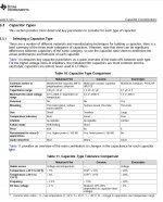
Here are never ending debates about the "best" input caps. My opinion:
-MLCCs coupling caps as found on many boards are the cheapest, the smallest - and worst ones.
-best ones are foil caps like the small Wima MKS.
-polarized electrolytic caps are fine as well.
-I do not advocate increasing capacitance beyond 1uF. This increases possible pop sounds on power turn-on without any other audible advantage.
-any input coupling cap with a physical size exceeding one lump of sugar is pure nonsense.
Last edited:
Maybe I am wrong and the output MLCCs do not degrade THD significantly. All in all the TPA3118 does not achieve top notch THD performance. But for a rugged solution I would ditch any MLCCs found in a power LC circuit.The first thing I would do is replace output filter MLCCs - they certainly will degrade THD.
It would certainly be entertaining to know the mechanism behind that one, given that output filter is making a new audio voltage incremental every 400kHz or so and its LP character starts to roll off at 60kHz or so.
There is actually a TI app note about output filtering for class D amps that rates the types of caps for audio performance. Film gets “best” and mlcc gets “worst”. Let me find it.
https://www.ti.com/lit/an/slaa701a/slaa701a.pdf
As a rule of thumb, i try to avoid things that are rated “worst” 🙂
As a rule of thumb, i try to avoid things that are rated “worst” 🙂
Attachments
Last edited:
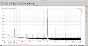
Furthermore I suggest THD-spectrum @1kHz/6kHz with ARTA at 2.82Vrms and 10Vrms with nominal dummy load. Giving plots like this one.
I’ve got some thd plots, but i’m not sure what arta is. I’ve been using REW, is there an arta option or something?
I definitely see a difference between the spectra of the amps i looked at. I’ll grab the, off the computer later.
Film gets “best” and mlcc gets “worst”.
This is well-known to be the case.
Besides REW, ARTA is the "other" common used audio SW. It is the one I use. But you will be fine with REW anyway.
Hi everyone,
As many do here, i have a pile of tpa3116 boards that vary in quality (and mods).
I’ve settled on a pair of the dayton branded Sure boards with integrated dsp, etc... sounds good, but I don’t know what their potential is.
Is there an objective way to measure the improvements of the input, bootstrap and output filter caps? I’ve found these boards to be better thought out than the cheap ones i’ve been playing with and don’t want to needlessly cut and slash to install wirewound caps and whatnot if it was 90% as good before.
I have access the standard EE tools: to a nice Tek scope and signal generator, usb sound interface, load resistors, etc....
I was planning to do some THD measurements, but i’m thinking that there should be specific things to look for and likely a specific test that will show how well the LC filtering is working.
Any thoughts?
You probably know this but if not - it's important. The TPA chips are BTL and do not refer to ground meaning you
will need special attention to monitoring the output. The output DC for each will be 1/2 of the power supply Voltage
relative to 'ground'. Do not connect scope ground leads of the scope to the '-' output pins. Easiest would be to treat
the outputs as 4 separate channels and sum the '+' and '-' using the math in the scope. I just want to save you the
possibility of damage to the amp.
G²
I knew that you couldn't connect the scope directly, but I didn't know the sum trick. then where would the scope probe grounds go? Just to the ground plane?
Incidentally, I have been using the technique of XRK Howto - Distortion Measurements with REW
Incidentally, I have been using the technique of XRK Howto - Distortion Measurements with REW
Hopefully it is safe to connect the ‘ground’ of the single-ended input of the audio interface box to the (-) of the amp. Now that i think more about this, perhaps it is not safe to do that.
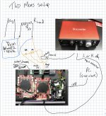
See attached pseudo schematic. I apologize for my horrible handwriting but these notes were just for me initially.
The second pic is of the run i did with the alternate tpa3116 amp.
I had to do some sneaky things to have an appropriate a/b comparison.
My signal chain is digital all the way to the DSP that is built into the amp, so i can’t easily tap into it to divert the signal to the alternate amp. I heard that the arylic up2stream may put some processing onto the signal so i wanted to make sure as much of my signal chain was identical. No need to chase amp problems that aren’t in the amp!
Anyway, in the DSP, i reconfigured the sub channel to be a duplicate of the signal going to the TPA3116 on the board.
I then took a spectrum of this analog output to use as a reference. For the alternate TPA amp runs, i merely connected it to this analog output. You can definitely see that there is higher noise floor when doing it this way because of the long wires, but that’s what we’ve got.
I think at this point, I’m looking for qualitative difference not quantitative.
Attachments
@Brianthechemist - thank you for posting the link to that TI app note.
In it they talk about "inductor linearity" and its effect on amplifier THD. This is a measurement you can actually make, if you have a spare N channel FET, a 10 mOhm resistor, a good function generator along with your oscilloscope.
We used a bazillion dollar Wayne-Kerr apparatus to do this, which was discovered to have insufficient capability for the inductor we were interested in, after we purchased the thing.
The basic circuit starts with a very well decoupled voltage source, usually lots of capacitance on the test fixture etch itself. One end of the inductor connects to this. The other end to the N-channel FET Drain. The FET Source connects to the 10 mOhm, through that component to ground. Drive the FET gate directly from the function generator, with a 50 Ohm terminating resistor. Use the scope to watch the signal across the 10 mOhm.
The idea is to slam the inductor to ground through the FET, using a pulse. When electronically grounded by the FET, current will rise linearly in the inductor - up to a point. You can start with a small pulse width and increase it, until the linear curve starts to bend - up - which is where the inductor is starting to saturate.
Of course, you have to be a little careful operating this, because when the inductor saturates, the FET takes a good beating, with only the 10 mOhm taking current against the FETs "on resistance".
If your function generator can do bursts, like, down to a single cycle, an enormous current can be generated with surprisingly small FETs. One guy was getting hundreds of amps from a FET that would fit on the end of a pencil eraser - single shot, repetitive at a few Hz. 20A should be no problem.
It's interesting that this performance aspect of an inductor effects amplifier THD in the critically audible 1 - 6kHz range.
I assume that you refer to the linearity of the current slope measured across the shunt resistor. With a storage scope at hand you even do not need any switching PowerMOSFET. Just charge an electrolytic cap - starting with 100uF charged upto 50V - and discharge it into the coil. Monitor shunt differential with a scope in single shot mode....
- Home
- Amplifiers
- Class D
- How to objectively decide to upgrade caps? TPA3116