I have an Eico HF-85 preamp which has a spec of 8000 ohms output impedance.
Using a Mcintosh MC 2255 amp with an input impedance of 50Kohms.
Not quite a 10:1 ratio, but I'm guessing it's still OK.
The gain of the HF-85 is fairly high, so even with my MC 2255 set on the 2.5V sensitivity setting, I'm thinking the gain may still be on the high side.
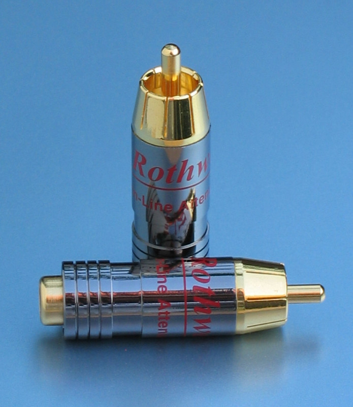
I have these -10dB Rothwell attenuators sitting around and wondering if I were to use these on the output of the HF-85, how the output impedance would be affected.
If it lowers the ratio materially, I may be better off doing without. If it doesn't meaningfully affect the output impedance or actually lowers it, I may be better off using them.
So looking for input on how these attenuators affect preamp output impedance.
Thanks!
Using a Mcintosh MC 2255 amp with an input impedance of 50Kohms.
Not quite a 10:1 ratio, but I'm guessing it's still OK.
The gain of the HF-85 is fairly high, so even with my MC 2255 set on the 2.5V sensitivity setting, I'm thinking the gain may still be on the high side.
I have these -10dB Rothwell attenuators sitting around and wondering if I were to use these on the output of the HF-85, how the output impedance would be affected.
If it lowers the ratio materially, I may be better off doing without. If it doesn't meaningfully affect the output impedance or actually lowers it, I may be better off using them.
So looking for input on how these attenuators affect preamp output impedance.
Thanks!
The answer to your question is almost certainly yes, but if you want a more useful reply...
Do you have any information about the attenuators other than their nominal attenuation? Assuming they are resistive attenuators and not transformers, could you measure their input and output resistance?
Do you have any information about the attenuators other than their nominal attenuation? Assuming they are resistive attenuators and not transformers, could you measure their input and output resistance?
The total resistance of the attenuator from its input to ground must be greater than 33k to keep
the LF rolloff with the 0.25uF output capacitor below 20Hz. That is possible, but should be checked.
The 8k preamp output impedance is high, and will interact with the attenuator to increase the amount
of attenuation from that specified.
Whether it increases or decreases the 8k preamp output impedance depends mainly on the attenuator's
resistance between its output and ground. That will be the effective output impedance, and if lower
than 8k, it will decrease.
Last edited:
The answer to your question is almost certainly yes, but if you want a more useful reply...
Do you have any information about the attenuators other than their nominal attenuation? Assuming they are resistive attenuators and not transformers, could you measure their input and output resistance?
Yes, they're definitely resistive attenuators. I couldn't find any pics of them deconstructed, so I can't say how the resistors are configured internally. But I'd imagine there's just 2-3 of them. For factor is like this:
Last edited:
The total resistance of the attenuator from the input to ground must be greater than 33k to keep
the LF rolloff with the 0.25uF output capacitor below 20Hz. That is possible, but should be checked.
The 8k preamp output impedance is high, and will interact with the attenuator to increase the amount
of attenuation from that specified.
These attenuators are intended to be used with solid state circuits, which have much lower
output impedance, and much larger values of the output capacitor.
Thanks. I won't use them then.
Do you think I'll get low frequency rolloff even if I don't use them, with 8K preamp output impedance and 50K amp input impedance?
Another question on this preamp. . .
The stock configuration uses a 0.25uF coupling cap right before the preamp output.
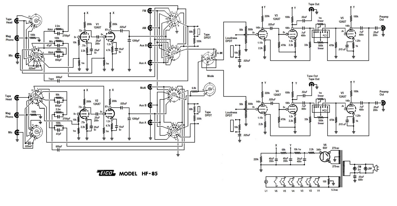
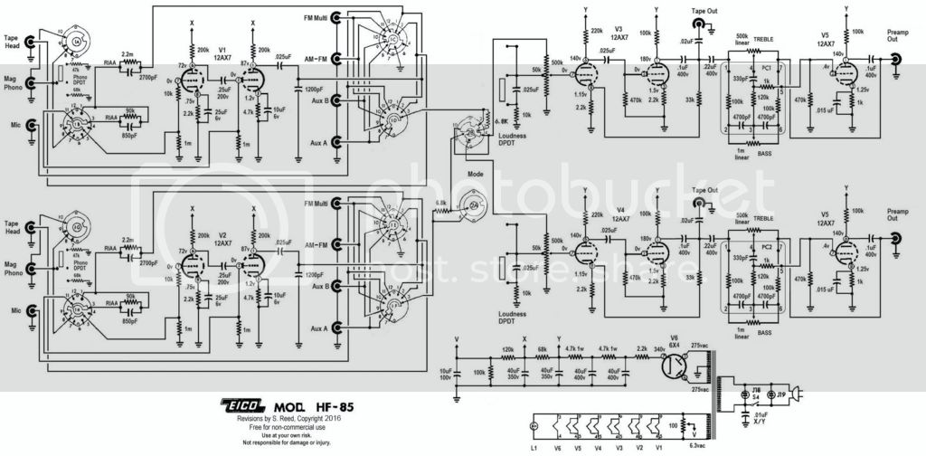
A recommended mod is to move that coupling cap earlier in the circuit, before the tone circuit, to avoid DC getting into the tone circuit and making it potentially noisy. Doing that removes it from right before the preamp outputs, as shown in the schematic below.
I don't know whether this mod affects output impedance at all, and if so, in what direction.
The stock configuration uses a 0.25uF coupling cap right before the preamp output.
A recommended mod is to move that coupling cap earlier in the circuit, before the tone circuit, to avoid DC getting into the tone circuit and making it potentially noisy. Doing that removes it from right before the preamp outputs, as shown in the schematic below.
I don't know whether this mod affects output impedance at all, and if so, in what direction.
That's probably worthwhile in this circuit. The output impedance won't be affected except
at very low frequencies, where it will decrease somewhat.
at very low frequencies, where it will decrease somewhat.
Do you think I'll get low frequency rolloff even if I don't use them, with 8K preamp
output impedance and 50K amp input impedance?
That would roll off at around 11Hz, mainly due to the 0.25uF output capacitor.
Removing the 0.25uF capacitor to elsewhere would decrease this further, because the remaining
output capacitor is within a 12AX7 unity gain feedback loop, and is effectively much larger.
Last edited:
Thanks for both answers @rayma!
Sounds like there's no practical issue with excessively high bass roll off between my preamp and amp due to impedance matching, but it's still beneficial to relocate that 0.25uF capacitor to reduce possible noise in the tone circuit.
Sounds like there's no practical issue with excessively high bass roll off between my preamp and amp due to impedance matching, but it's still beneficial to relocate that 0.25uF capacitor to reduce possible noise in the tone circuit.
Not sure if that will make a difference for the pots, as there is no visible DC current path through them,
either way. But the LF roll off frequency of the tone stage would be much lower after moving the capacitor.
Mainly, that will reduce the LF phase shift below 100Hz.
either way. But the LF roll off frequency of the tone stage would be much lower after moving the capacitor.
Mainly, that will reduce the LF phase shift below 100Hz.
Last edited:
... the pots, as there is no visible DC current path through them, either way. ....
There is a sneak path. I'm shocked, because I ran such preamps for years and never noted this. Or had DC scratchies.
The line amp gain seems to be 15. In a world of 2V sources, this is too much. If all sources are near 2V, the place to pad is *before* this tube, unless you like a little distortion. Turn the VOLume knob down generously. Even consider putting that 10dB pad between the CD/DAC and the EICO input.
Attachments
Don't know what's in the Eico PC-1 module, maybe so.
The Dyna PAS-2 preamp did have DC voltage at the output, but when revising it to the PAS-3x
they added a small electrolytic coupling capacitor before each output. Quick and dirty fix, literally.
The Dyna PAS-2 preamp did have DC voltage at the output, but when revising it to the PAS-3x
they added a small electrolytic coupling capacitor before each output. Quick and dirty fix, literally.
Don't know what's in the Eico PC-1 module, maybe so.
The Dyna PAS-2 preamp did have DC voltage at the output, but when revising it to the PAS-3x
they added a small electrolytic coupling capacitor before each output. Quick and dirty fix, literally.
In the second schematic of post#6, it shows what's actually inside the PEC. My friend who I got this from implemented the PEC w/new discrete components.
He basically did a whole tear down and rebuild just reusing the original transformer and working to the original circuit, though he chose to simplify by removing the tape output and loudness circuit. I guess he didn't see the modified schematic that moved the coupling cap before the tone ckt and the additional power supply cap.
I'm listening to it now. I hear a very small amount of hum when no music is playing, but I need to put my ear near my speaker to hear it. Can't detect it from my listening position even when preamp volume is turned up higher than I'd actually use.
There's a power supply mod in the 2nd schematic as well. I guess there's insufficient B+ filtering in stock form which may lead to a 120hz hum (maybe that's what I'm hearing). The modified schematic splits the 10K resistor into two 4.7K's and adds another 40uF cap between for better filtering.
Because I can't hear the hum from my sitting position, I likely won't be in a rush to make the mods, but will probably be something I do eventually as I understand it's more robust to make those mods.
I'm using the Rothwell attenuators for one of my sources to try them out there. My phono stage has very high gain (55dB) and is louder than a normal CD source with the cartridge I'm using. Adding the attenuator brings it closer to the level of my disc player.
Sounds really good. . .a nice preamp.
In the second schematic of post#6, it shows what's actually inside the PEC. ....
As expected, a Baxandall. (What else?)
However there's an inconsistency. The 2nd in #6 has a final cap moved to the middle. BUT the DC voltage on the last grid implies no such cap. While a few-tenths Volt on 12AX7 grid is not a shock, 0.4V is too suspiciously close to what 1.15V through the Bax and the 470k works out to be.
Attachments
As expected, a Baxandall. (What else?)
However there's an inconsistency. The 2nd in #6 has a final cap moved to the middle. BUT the DC voltage on the last grid implies no such cap. While a few-tenths Volt on 12AX7 grid is not a shock, 0.4V is too suspiciously close to what 1.15V through the Bax and the 470k works out to be.
My guess is whoever created the 2nd schematic made certain modifications (moving that 0.22uF cap, changing the tap point of the Tape Out jack, modifying the power supply ckt at the bottom of the schematic), but they may have forgotten to erase that 0.4v on the last grid.
Would that make sense and resolve the inconsistency?
- Home
- Source & Line
- Analog Line Level
- Do Inline Attenuators Change Preamp's Output Impedance?