Hello,
For the past several months I have been slowly learning and developing a two way speaker using the RS150P-8A and XT25TG30-04. Many of you on this forum helped me get my measurement issues resolved and my technique up to par and I am very grateful.
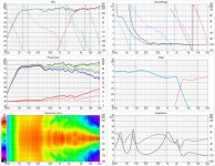
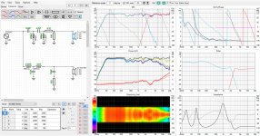
I would like to start a discussion on the recent attempts I have made in crossover design using VituixCAD. It is an amazing software but... "with great power comes great (complexity)". I now have a full set of 180 hor and ver measurements loaded and can report on my first full sim attempt using this software.
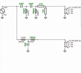
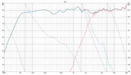
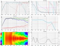
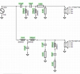
I have attached images that show the VituixCad Sim, the circuit design and the real world measurement results.
It looks like I have some small variations between the sim and the real-life result. Should I expect better agreement? If so where should I look to resolve the issues? One area in the back of my mind is the setting of mic distance in the REW measurements...
While measuring I used the on axis measurement to use as the distance/timing reference. Would I have better results if I readjusted the timing to say...30-40deg? It would be more of an average of the source distance.
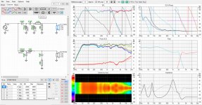
Anyway. I had good enough agreement to begin work on a new version of the crossover. (images labeled "New Crossover Candidate")I have the sim and circuit images below. Comments are more than welcome.
And thank you so much again for all your help!
Best Regards,
J.
For the past several months I have been slowly learning and developing a two way speaker using the RS150P-8A and XT25TG30-04. Many of you on this forum helped me get my measurement issues resolved and my technique up to par and I am very grateful.
I would like to start a discussion on the recent attempts I have made in crossover design using VituixCAD. It is an amazing software but... "with great power comes great (complexity)". I now have a full set of 180 hor and ver measurements loaded and can report on my first full sim attempt using this software.
I have attached images that show the VituixCad Sim, the circuit design and the real world measurement results.
It looks like I have some small variations between the sim and the real-life result. Should I expect better agreement? If so where should I look to resolve the issues? One area in the back of my mind is the setting of mic distance in the REW measurements...
While measuring I used the on axis measurement to use as the distance/timing reference. Would I have better results if I readjusted the timing to say...30-40deg? It would be more of an average of the source distance.
Anyway. I had good enough agreement to begin work on a new version of the crossover. (images labeled "New Crossover Candidate")I have the sim and circuit images below. Comments are more than welcome.
And thank you so much again for all your help!
Best Regards,
J.
Attachments
Basic rules shortly:
1) Direct (X-ray) physical distance from baffle surface at the center of each DUT to mic should be constant e.g. 1000 mm while all far field measurements. Same distance with all drivers and all off-axis angles. Simple as sh*t.
2) Sound flying time of direct physical measurement distance e.g. ~2.91 ms with 1000 mm should be removed from all far field responses while converting measured impulse responses to frequency responses. Same time from all drivers and all angles. Simple as sh*t.
Note: Constant time offset should be longer if there is DSP device outside reference channel loop. For example if loop back is connected from output to input of sound card, and signal to driver travels through amplifier having constant processing latency >0 ms, you need to remove more than 2.907 ms with measurement distance of 1000 mm.
3) Real life QC measurements from complete speaker should be taken at Listening distance set in Options window. Not at 1000 mm because distances from each driver to mic will not be equal to simulation where virtual mic is typically at 2-3 meters from origin of the speaker. Long distance requirement means that reliable full space measurements from complete speaker need decent acoustic lab or large free space. Therefore it's possible that simulation is more accurate than QC measurement. For example I never compare simulation result to real measurements. Just verify that basic things such as polarities, levels and phase match of the highest XO are okay.
For me, phase tracking of the drivers in the XO area is important, I would try to tweak the design to get them basically on top of each other in the overlap area, maybe down to -15dB or more if you can. IMHO good phase tracking improves depth perception when you listen.
I also find it helpful to be able to insert target FR slopes in the graph and try to match that, but I'm not familiar with VC. I find that high (acoustic) Q can sound disturbing/tiring.
I also find it helpful to be able to insert target FR slopes in the graph and try to match that, but I'm not familiar with VC. I find that high (acoustic) Q can sound disturbing/tiring.
Last edited:
Thank you for the quick response! I apologize for my delay. Life just gets in the way sometimes. I do have just a couple clarifying questions.
1) The mic should be constant distance from the baffle surfaces and at the center axis of each driver being tested...
In my testing setup, the measurement distance to the mic was fixed at 1 meter to the baffle surface, on axis,
and on the driver center for each driver tested. This was accurate to within about +/-5mm on axis.
All of my measurements were taken at this fixed distance, with the mic stationary and only the platform/speaker rotating.
As the platform is rotated the distance from driver to mic increases due to the rotation, with the most extreme case
(180 deg) my speaker's baffle surface will be an additional 350mm (approx.) away from the measurement microphone.
Then I set all measurements (0- 180 deg hor in 10 deg increments) in REW to reference the original on axis measurement
distance (0 deg hor).
I was under the impression that the physical measurement distance changing due to rotation was expected, encoding
valuable phase information and other data, and that we should dictate the constant 1 meter measuring distance to REW as reference. Thanks for all of your help and seemingly infinite patience for the new comers.
2) I did fine tune the 0 deg measurement by selecting "Estimate IR Delay". My hope was that this small change adjusted for temperature and altitude as well as any few mm I was off with the setup. Is this good practice or should I remove that and use the 2.907ms (1M) for all measurements?
Cheers!
2) I did fine tune the 0 deg measurement by selecting "Estimate IR Delay"... Is this good practice or should I remove that and use the 2.907ms (1M) for all measurements?
Measurement data is destroyed if program estimated different IR delay for different drivers and different value was subtracted from IR of different drivers. Nothing like that is recommended in my documentation for 100% sure so it's unacceptable.
As already said; constant time can be subtracted from all far field measurements. 2.907 ms or 2.92 ms or 2.94 ms with 1 m distance. Value itself does not matter much, but it must be exactly the same for all drivers and angles to maintain timing differences between drivers and off-axis angles, assuming that physical measurement distance was constant. That's whole point of dual channel measurement connection and mode.
Thank you! I still have the raw data and can revert to the 2.907 ms for both drivers. I will try this and see if I get better agreement from the Sim to real life measurement. Also, thanks for the tip on measuring from the simulated listening distance. That makes sense.
One concern I have, is that when I had to lay the speaker on it's side for the Vertical measurements I may have disrupted the distance to microphone by a few mm (+/- 5-10mm). Is this a problem? Does keeping the same timing offset (2.907 ms) still work?
One concern I have, is that when I had to lay the speaker on it's side for the Vertical measurements I may have disrupted the distance to microphone by a few mm (+/- 5-10mm). Is this a problem? Does keeping the same timing offset (2.907 ms) still work?
Both Drivers.
After the horizontal measurements I laid the speaker on it's side and slid the mic to the L/R to align with the center of the driver being tested. I did my best to hold it to exactly 1 meter but it's a little loose. I estimate 5-10mm error.
It concerned me enough I was considering building a jig/ rail system that helps me stay at exactly 1 meter and perfectly square with the baffle orientation. I thought that by using the "Estimate IR delay" function I could at least get a standard timing offset to index the rest of the measurements to.
^I meant driver model, but they seem to be circular; dome and cone. Vertical plane is optional with circular radiators, depending on mechanical symmetry of the cabinet and possibilities to perform vertical measurements or laziness of the designer.
One option is to ignore vertical measurements and load horizontal plane only. 'Mirror missing' setting copies hor -> ver internally in the program. That would probably cause ca. 0.5 dB error (dip at mid) to power response which is not a big deal if you prefer axial response anyway at mid-range.
Second option is to compare timing of vertical and horizontal measurements to -10, 0, +10 deg with Calculator tool by looking phase responses. Adjust Delay [us] of vertical response group with Calculator if difference is more than 5 mm (~15 us). Function is 'Scale, Delay, Invert A'.
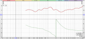
I need some help understanding the 90 degree phase difference between my woofer and tweeter. My thought is that this is due to merging the rear port with the near and far measurements. Is this correct?
Should I be converting this merged response to minimum phase?
I'm thinking about just using my far field responses (windowed to 5-6ms) to design the crossover so that I can see better phase agreement. How would you proceed?
Should I be converting this merged response to minimum phase?
I'm thinking about just using my far field responses (windowed to 5-6ms) to design the crossover so that I can see better phase agreement. How would you proceed?
It is the difference that counts. I can't imagine both drivers gave the same number. Adding 2.907ms to each is the same as leaving them at zero. Once you zero both, you lose the difference.and can revert to the 2.907 ms for both drivers.
I can't tell whether VC is ignoring vertical summing or simulating it, or combining horizontal with vertical here.. but I see your DI is close, you might not want to mess with it as much as that.I need some help understanding the 90 degree phase difference between my woofer and tweeter.
Same answer as setting the timing to zero.Should I be converting this merged response to minimum phase?
I have believed that measurement and data processing instructions for ARTA, REW and SoundEasy and user manual and sample projects cover "everything" necessary, but optimism has changed to desperation 🙂
Maybe documents are crap or users don't read them carefully or traditions have damaged brain so much that it's impossible to recall what is measuring timing/phase differences within 0-180 deg, and why it's mandatory in case crossover is simulated with acoustical frequency responses to full space.
Documents should also include some answer to minimum phase question(s). Fundamental form of minimum phase response does not exist in real life with speakers (0-180 deg) so whole thing is worth to forget from measurement toolbox. R.I.P. minimum phase and all white papers and tools where it's recommended or forced.
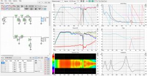
Here is a puzzle in VituixCAD. After running the optimizer I obtain a SPL result (Result1). I then check the phase agreement by inverting the tweeter (Result1 Inverted). When I return the tweeter to the "normal" phase, the response around 2.5K has had a dramatic shift.
Any help is much appreciated.
Best Regards,
J.
Any help is much appreciated.
Best Regards,
J.
Attachments
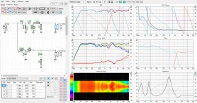
Here is a puzzle in VituixCAD. After running the optimizer I obtain a SPL result (Result1). I then check the phase agreement by inverting the tweeter (Result1 Inverted). When I return the tweeter to the "normal" phase, the response around 2.5K has had a dramatic shift.
Any help is much appreciated.
Best Regards,
J.
I couldn't get the optimizer of Vituixcad working. IMO it is a fantasy option.
Ugg10, good catch on the inductor! My apologies for my waste of a post.
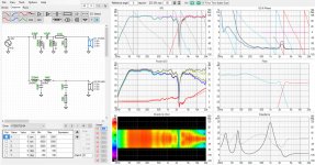
During that earlier post I took an intermediate step to see if I was crazy and I failed to notice the inductor value change. It seems the optimizer is bouncing between those two values 220/270mH.
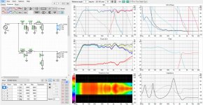
This error/ effect is present in all circuits to some degree. It's definitely more pronounced in the circuit with the 270mH inductor on the tweeter. I'm not sure if this helps track down the issue.
I have included another set of 3 screenshots. The only action taken between shots is to invert the polarity of the tweeter and then invert once again back to original polarity. Something is definitely off.
Thank you for your time on this!
J.
During that earlier post I took an intermediate step to see if I was crazy and I failed to notice the inductor value change. It seems the optimizer is bouncing between those two values 220/270mH.
This error/ effect is present in all circuits to some degree. It's definitely more pronounced in the circuit with the 270mH inductor on the tweeter. I'm not sure if this helps track down the issue.
I have included another set of 3 screenshots. The only action taken between shots is to invert the polarity of the tweeter and then invert once again back to original polarity. Something is definitely off.
Thank you for your time on this!
J.
Attachments
- Home
- Loudspeakers
- Multi-Way
- REW/ VituixCAD Crossover Design