I am building one of Pete Millett's HV Regulated Power SUpplies, and posted about it, but apparently in the wrong place (i.e. no traffic):
https://www.diyaudio.com/forums/equipment-and-tools/212518-pete-milletts-bench-power-supply.html
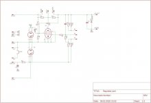
As part of the process, I redrew the schematic so that it's like a conventional regulated power supply schematic (mostly so that I could better understand what's going-on), i.e. Pass Tubes, Error Amp, Regulator tubes, top-to-bottom. See attached.
In this form, it looks much simpler and lots easier (at least to my old eyes).
If anybody wants to tinker with the schematic, I can post it here or send via PM.
Also, the original post has questions & comments, particularly about using sweep tube (6AV5GA) pass tubes, so take a look...
https://www.diyaudio.com/forums/equipment-and-tools/212518-pete-milletts-bench-power-supply.html
As part of the process, I redrew the schematic so that it's like a conventional regulated power supply schematic (mostly so that I could better understand what's going-on), i.e. Pass Tubes, Error Amp, Regulator tubes, top-to-bottom. See attached.
In this form, it looks much simpler and lots easier (at least to my old eyes).
If anybody wants to tinker with the schematic, I can post it here or send via PM.
Also, the original post has questions & comments, particularly about using sweep tube (6AV5GA) pass tubes, so take a look...
Attachments
Pete Millett HV Power Supply- Original Schematic
Here's PMillett's original schematic.
R12 is indeed 27K.
That seems about right for this voltage divider "stack". Typically the resistance ABOVE the voltage selector pot is slightly higher (37K) than the resistance BELOW the stack (25K).
This is what I would call a "low resistance" stack, i.e. totalling about 200K round numbers.
Classic regulated tube power supplies (Heathkit, EICO, Fluke, etc) use a ~1MM ohm stack with a 500K adjustment pot.
My guess is that Pete wanted to use a multi-turn voltage adjustment pot, which are only commonly available in 100K. This is one of the things I liked about this circuit.
I did the same thing in a rebuilt of a Heathkit PS-3, taking design cues from an HP regulated PS. Worked good, and those Bourns multi-turn pots are really nice to the touch.
Attachments
First B+ cap voltage
On Pete Millet's original schematic, this cap (before the B+ choke) is actually C3 and is 40uF at 370 volts (!!).
I changed the designation to C5 so that the main cap bank was C1-C4.
DC voltage before the choke should be HIGHER than after the choke (due to the DCR, dc resistance of the choke. Since the before-choke voltage is not yet well filtered, perhaps the RMS is lower...dunno (that is, if it's not a mistake).
In any case, I actually INCREASED it to 450V from the original, but meant to ask Pete about that before I warmed-up the soldering station...
I have some nice Russkie 600V oil caps I could use, if I can find the room.
Ironically, or perhaps comically, they are PINK.
On Pete Millet's original schematic, this cap (before the B+ choke) is actually C3 and is 40uF at 370 volts (!!)....
370V AC!! (A motor-run cap.)
Such a cap would logically stand 1.414 times that for some unspecified time. Which is 523V DC.
However one of the several schems in this thread shows 379(!) VAC making 535.9VDC. So 13 V above the assumed cap rating.
Got a face mask?
Makes sense. Well except the 370V part.
I'll have to take a look at the oil cap stock.
I would like to build from existing inventory, but if all I've got is the Pinko Oil Caps, it's going to be a tight fit to get even 20uF under the chassis. May need a trip to PSUD.
I'll have to take a look at the oil cap stock.
I would like to build from existing inventory, but if all I've got is the Pinko Oil Caps, it's going to be a tight fit to get even 20uF under the chassis. May need a trip to PSUD.
Yeah, I just found a bunch of 500V ones of those. Frankly didn't know they made a 600V version...good find.
'Cept I'm usually a Mouser guy (collecting a Trinket Order as we speak)..
Seems like Mouser caters more to the small-order hobbyist, but that could just be me.
Oh, and THIS guy:
Component sourcing and Mouser vs. Digikey Pros and Cons | LowPowerLab).
'Cept I'm usually a Mouser guy (collecting a Trinket Order as we speak)..
Seems like Mouser caters more to the small-order hobbyist, but that could just be me.
Oh, and THIS guy:
Component sourcing and Mouser vs. Digikey Pros and Cons | LowPowerLab).
Mouser sells it too, it's more expensive though, and shipping is 20$ at Mouser vs 8$ at Digi-Key (unless you order 100$, then both are free).
Both have their place... Digikey will ship heavy transformers for free, Mouser might not depending on how heavy they are, for instance.
Also, LCSC is great for passives and some other stuff, but shipping can be costly. Electronic Components Distributor | JLCPCB & EasyEDA Parts Online store - LCSC.COM
Last edited:
Well, I have to admit to Comparison Shopping Digikey & Mouser, but haven't used LCSC.
Mouser is practically next door (which in TX means a fast 4 hour drive) in Manfield, Texas (between Dallas & Fut Wuth), so I frequently get packages OVERNIGHT at regular shipping rates.
I had a colleague decades ago named Mouser. I asked where that name came from; he said that it was Mauser back in Germany, but some bored clerk at Ellis Island changed it to "Mouser". Might have been right around the Great War, when the House of Hannover became the House of Windsor.
A frat brother of mine played baseball for the Parmalat semi-pro team in Italy.
They were allowed only two Yanks, so they recruited Italian-Americans who could get Italian (dual) citizenship if they had direct male lineage. Unfortunately, Ellis Island had changed the family name from DiMarco to DeMarco, which apparently doesn't exist in Italian. Had to legally change his name to the proper DiMarco. Had to enter Italy on a tourist visa on US Passport to avoid compulsory military service, however. Ended-up pitching for the Italian Olympic baseball team against Team USA (!)
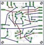
Tube Reg boards
I got about twelve to fifteen designs for various tube based regulators if anyone needs the boardfiles, just PM me your email and il send them to you.
Attached:
I got about twelve to fifteen designs for various tube based regulators if anyone needs the boardfiles, just PM me your email and il send them to you.
Attached:
- Control amplifier and reference section board on 100x100mm
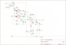
- Negative voltage tube regulator based on the tektronix 567 power supply
- Maida regulator with EL36/PL36
- Simple EL34 emitter follower. (Simplereg MK1)
Attachments
-
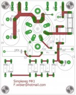 Simplereg MK1.jpg115.7 KB · Views: 125
 -
 PL36 maida.jpg47.2 KB · Views: 180
 -
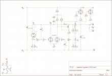 Negative tube reg schematic.jpg46.7 KB · Views: 194
 -
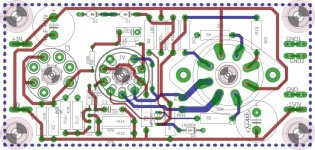 Negative tube reg board.jpg125 KB · Views: 155
 -
 E83F control amplifier 85A2 reference SCHEMATIC.jpg39 KB · Views: 152
 -
 E83F control amplifier 85A2 reference PCB.jpg68.9 KB · Views: 163
- Home
- Amplifiers
- Power Supplies
- Millett HV Power Supply Redrawn Schematic