re: those two drawings - they look like regular but low tuned BP6B* to me (*parallel tuned). What am I missing ? (besides brainpower)
Off-Axis 6th Order Parallel Bandpass Enclosure Calculator - DB DYNAMIX AUDIO
Thats a great and clearly colored example! Now it just needs ‘lengths in a qw or hw of a qw(harmonic) intervals to split it up as airmasses (with a long dimension) or folded segments such that reach a ratio between loading the cone or changing the phase to reach nirvana at exit (theres an issue with the exit of ‘x’ amount of ‘path’ (as referred to in hornresponse) but theres no folding in hornresponse either) so we are all scratching our heads from any perspective or observation. Akabak isnt the answer, though ive barely dabbled in its guts to find that out and look.
Last edited:
Bro, this seems to me like a horn+bp+tl kinda, how could you even sim this...? I can't imagine that insane build. Okay, to be honest, I've leart to some extent from a few online resource about some subwoofer enclosures types and their behavior, but haven't dug deep in physics, even my thread title implies I'm not a subwoofer builder, actually I'm not, my subject is computer science though a bass lover.
I'll tell you the real story here, a friend of mine, a subwoofer builder, is excited about my design, but he doesn't know how to sim/mod it, what he really does is (and almost all subwoofer builders in our country) just copying the recognized factory-made subs (most of them are made in your country), so that can never be faulty as the dimensions are original, and he's great at constructing them.
Thus, our country has a great manpower/labour, but what lacks is the engineering skill, that's the common lack in everything in here, that's why we're still a developing country, it's a different story, irrelevant to you, just saying...
BTW, how about the 2 below...?
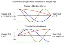
If we use a common straight ‘pipe’ instead of a chamber and reduction theres somewhat of an easier group of ‘ideas’ to absorb for us as non acoustical engineering types 🙂. After the fact we must address the way to fit the driver, but that too will be used in a similar proportion of the same ‘lengths’! Its all snowballing into a potential result at the end(including the ‘room’ if youre lucky enough to be able to use the same (larger scale ) dimensions.... but if assuming you can then its boiled down to a simple folded pipe on each side (or folded once, or 3 times, to remove the harmonic void/cancel/trough.....
Last edited:
Maybe its the ‘3:1’ that should be ‘2:1’ and 3:1.......
I don't have a clue what you're trying to say, much less accomplish; I mean pipes are 1/4 WL resonators and octaves are a 2:1 ratio, so where does this 3:1 ratio come from other than as driver compression ratios? Can't recall ever using it in any box alignment, though haven't done much with DBRs other than with octave ratios, so might have some use there.
Also, if you want sections of pipe to resonate at differing harmonics, you have to create an acoustical impedance mismatch such as done with many BVR/BLH designs where only the prime fundamental and its first few harmonics [at most] make it through in ~one piece: The Spawn Family of Double Horns
1/3: 3/3, generic wording for the length required to an offset stub (driver entry) to fill in the first harmonic void in response. Or ~33%
Compare: vent exit and driver at same position on the ‘box’ exterior.
Closed end
80 cm
Driver entry
80 cm,
80cm
Exit
————-
Total 240cm
Then,
Driver entry at closed and
80,80,80cm
Exit
Total 240cm
What changed?
A lot if looking at the response in a sim.l for a 240cm piece of pipe. Straight.
But What happens if we fold that 240 cm into (3 pipes) as two 180 degree turns at 80 cm each?
Its now an open ended pipe centered with two equal pipes at each end(reflection as the overall pipe exit and an actual closed end in one).
This has its own unique conclusions to sum at exit. And drawn in the oneside the earlier pic and shown to not work out in the other(as a compunded horn version) unless ‘maybe’ that didecis folded in TWO(?)
Attachments
Last edited:
I'm gonna call a doc before you... 😀
BTW, I'm a bit confused of some you mentioned here.
Thanks bro! 🙂
Why do you suggest I should join the exits (as in the original sketch I drew right?), and reflection is hinted in which drawing then...?
How (or from where) could you find these dimensions...?
BTW, I'm a bit confused of some you mentioned here.
If applied to a length and a driver its easy to sim. Ill gladly help you!! 🙂 thumbs up:
But if you join the exits or seperate them by an infinite length. A sim has you seated a 1 meters distance in a generic boundary thats confusing me more and more because of another reflection.....
Thanks bro! 🙂
Why do you suggest I should join the exits (as in the original sketch I drew right?), and reflection is hinted in which drawing then...?
The drawing tells me if everything is 80 cm on the left, the right hand side has an issue if divided by 3 (then its 80/3) instead of two (40 x2) or just as one (80cm x1) alone? Size matters aswell, and a Crossectional area reduction or bulk increase would change this in a sim. It gets quite confusing after that , but ‘folding’ is where i sit and 180 degree folds with a little extra ‘kink’ to ensure they divide the low pass affect or reflected HF material to get absorbed and reflected again in an ingoing cycle of “2” so to speak?
How (or from where) could you find these dimensions...?
GM is a DIY geeks hero. He has a value as an encyclopedia of resources and facts that is unmatched and greatly appreciated by many many many many!!
Great! 👍
Ive been using this for quite awhile. But theres too much to ‘test’ and its all missed and left in the folding(?) not represented in a sim... the last frontier should be obvious. I dunno why its not ‘used’ or ever has been, but i do know my ideas and explanations suck, lol!
True, you made me a lunatic bro, I'm barely conscious now...

re: those two drawings - they look like regular but low tuned BP6B* to me (*parallel tuned). What am I missing ? (besides brainpower)
Off-Axis 6th Order Parallel Bandpass Enclosure Calculator - DB DYNAMIX AUDIO
Yes you're, look carefully at my drawing, when placed on the floor my both ports look horizontally, the higher-tuned one from the front chamber is upper to the lower-tuned one from the rear chamber, it has a logical point of view, the below 20hz region is positioned underneath the above 40hz region, so that's what I think my design makes irregular to generic SBPs.
It wasnt until i chopped the top panel off this offset driver TL in an effort to create a clear acrylic window on its entire length and segments to look thru and guide the magnet/microphone( inside glass cleaner tool for a fish tank) along its way to find the ‘null’ and at varius frequencies maybe ‘more’ that i realized i had to divide it into equal sections to protect the thin ‘acryillic from flexing. The sections would be wooden windows as a result, but a cross brace in that frame of window pane grid might block my view/access to the actual null or area in question would result. Thats when it became obvious that folding is its own division and exaggeration of the main pipe(2 once the rear section is added to this or removed).
This is just an ‘offset entry Pipe’ with 100cm and 200cm from each ‘end’. The drivers at about 110 if you skew the idea of the tilt required to fit that into the CSA required for ‘Vas and Qts/Fs. with the least ‘stuffing’ (in sim) or similar attempts to control things otherwise..
Wow, that TL, love it... 😎
If we use a common straight ‘pipe’ instead of a chamber and reduction theres somewhat of an easier group of ‘ideas’ to absorb for us as non acoustical engineering types 🙂. After the fact we must address the way to fit the driver, but that too will be used in a similar proportion of the same ‘lengths’! Its all snowballing into a potential result at the end(including the ‘room’ if youre lucky enough to be able to use the same (larger scale ) dimensions.... but if assuming you can then its boiled down to a simple folded pipe on each side (or folded once, or 3 times, to remove the harmonic void/cancel/trough.....
So, that's what makes ypu my saviour... 😉
As presented, nothing.
But, here's the reply I wrote to him, what's your opinion (heard from "Booger weldz" you're expert)?
Yes you're, look carefully at my drawing, when placed on the floor my both ports look horizontally, the higher-tuned one from the front chamber is upper to the lower-tuned one from the rear chamber, it has a logical point of view, the below 20hz region is positioned underneath the above 40hz region, so that's what I think my design makes irregular to generic SBPs.
I don't have a clue what you're trying to say, much less accomplish; I mean pipes are 1/4 WL resonators and octaves are a 2:1 ratio, so where does this 3:1 ratio come from other than as driver compression ratios? Can't recall ever using it in any box alignment, though haven't done much with DBRs other than with octave ratios, so might have some use there.
Also, if you want sections of pipe to resonate at differing harmonics, you have to create an acoustical impedance mismatch such as done with many BVR/BLH designs where only the prime fundamental and its first few harmonics [at most] make it through in ~one piece: The Spawn Family of Double Horns
I can't believe my eyes, how well enginnered they're, heavenly... ❤️
LoL!! Im trying to explain the phase shared by adding various ‘extras’ to a common qw pipe, using the same exact driver and pipe in each different version
It might show what youre doing in actual wavelengths, vs a chamber and a port(paired in this case). The idea that your example currently ‘cancels’ from 3x Fb in qw can be seen in a sim where it indeed begins to remove response from the top down as you add the short port on the high tuned side from 0-40/60/80...cm(etc) assuming that 40/60 or 80 is equally distributed as 40/60/80(x3) on the Low frequency side. Matching crossectional areas and lengths as pictured in your drawings.
240cm is mid 30hz and 80cm is 105hz...
A good example of this is an offset driver qw pipe, or compound qw pipe , or a Tapped qw pipe with qw resonator, or offset resonator... phase for the same 240cm)(80cm x3) is a variety of things if you attach 80 cm extra to acheive a variety of needs. But that 80 cm cannot be 160, or 240 it cancels all the way to that length and leaves a void(notch). But it can be located as a ‘stub’ filled with polyfill and the void becomes a beautiful bandwidth if you choose to stick a long skinny chamber someplace strategically.
But in this scenario ot cannot exceed or be less than 80 cm either, as it begins to or create nasty phase summation otherwise. A big squiggle shape or void will result. This assumes a constant csa pipe(straight) for all 80cm (and 240cm on the other side). Change the CSA (expand) and the game changes... big time!
Recently, i built a qw pipe to ‘bolt on’ a variety of these (as a 100cm add on)to an existing 300(100x3)cm qw pipe. Rain and glue curing takes forever and paint is even less likely... but im almost done with the main qw pipe amd driver is broke in..
I have built almost every kind of qw pipe i can think of, but since they were all designed to be ‘perfect’ essentially, the actual ‘learning’ is still not what it could be. I have to make ‘bad’ and find it inside the pipe as a null. A magnetic fish tank glass cleaner will drag the microphone around in the oipe with varoius attachments... looking for the odd harmonic or (??) in a way i never had exactky. I lost my dars v3 and smart phone in an enclosure vent like yours(lf side) recording a slomo video of test tones inside... still gotta cut it open to get them out😀
Last edited:
LoL!! Im trying to explain the phase shared by adding various ‘extras’ to a common qw pipe, using the same exact driver and pipe in each different version
It might show what youre doing in actual wavelengths, vs a chamber and a port(paired in this case). The idea that your example currently ‘cancels’ from 3x Fb in qw can be seen in a sim where it indeed begins to remove response from the top down as you add the short port on the high tuned side from 0-40/60/80...cm(etc) assuming that 40/60 or 80 is equally distributed as 40/60/80(x3) on the Low frequency side. Matching crossectional areas and lengths as pictured in your drawings.
240cm is mid 30hz and 80cm is 105hz...
A good example of this is an offset driver qw pipe, or compound qw pipe , or a Tapped qw pipe with qw resonator, or offset resonator... phase for the same 240cm)(80cm x3) is a variety of things if you attach 80 cm extra to acheive a variety of needs. But that 80 cm cannot be 160, or 240 it cancels all the way to that length and leaves a void(notch). But it can be located as a ‘stub’ filled with polyfill and the void becomes a beautiful bandwidth if you choose to stick a long skinny chamber someplace strategically.
But in this scenario ot cannot exceed or be less than 80 cm either, as it begins to or create nasty phase summation otherwise. A big squiggle shape or void will result. This assumes a constant csa pipe(straight) for all 80cm (and 240cm on the other side). Change the CSA (expand) and the game changes... big time!
Recently, i built a qw pipe to ‘bolt on’ a variety of these (as a 100cm add on)to an existing 300(100x3)cm qw pipe. Rain and glue curing takes forever and paint is even less likely... but im almost done with the main qw pipe amd driver is broke in..
I have built almost every kind of qw pipe i can think of, but since they were all designed to be ‘perfect’ essentially, the actual ‘learning’ is still not what it could be. I have to make ‘bad’ and find it inside the pipe as a null. A magnetic fish tank glass cleaner will drag the microphone around in the oipe with varoius attachments... looking for the odd harmonic or (??) in a way i never had exactky. I lost my dars v3 and smart phone in an enclosure vent like yours(lf side) recording a slomo video of test tones inside... still gotta cut it open to get them out
Sorry for my late reply bro, I was a little busy...
Understood, this reply from you finally relieved me, I could take a breath. 😀
So, the only thing I'm asking now, please show me your mod of my design. 🙂
BTW, what do you think may have happened to your smartphone by now? 😛
Smart phone has been replaced, lol!
altering your design is only to use qw appearance instead of helmholtz action at random?. (meaning qw pipe resonance vs pressure cavity
Fart across them maybe? Ones kinda weird and not always.. the other is less weird, lol!
The pipe has to be folded, its got plenty of weird (but useful/good) harmonics and backwaves because of it and the ‘tapped/compounded’ entry locations provide the doubling of that affect? Cancel or support is now a tool not-an issue. Its only relevant at harmonic intervals in some ways More than others?
But i get lost about this deep in and thats where i deviate from the course everytime. Because i dont know ‘sound’ i only know collisions and thermo stuff from the nuclear power industry. And thats been quite awhile so what of this maybe? This video:
Acoustic Energy & Surprising Ways To Harness It (Intro To Thermoacoustics) - YouTube
Last edited:
But i get lost about this deep in and thats where i deviate from the course everytime. Because i dont know ‘sound’ i only know collisions and thermo stuff from the nuclear power industry. And thats been quite awhile so what of this maybe?
How could you build such amazing subs which you've posted here if you really don't know about "sound" bro??? 😕
I'll watch the video you linked btw, thanks... 🙂
Any comments...?
I dunno if its relavent or which parts. But unless you define things much more specifically, none of it is. Unfurtunately, that gets harder to describe by typing and then the idea gets lost in other ways. I tend to try, but just end up confusing people(myself included).
Plot out your idea and use qw lengths and folding at 180 degrees(the turn as a
Shape is a switchback, not the ‘degrees of phase’, theyre different things, but confusing...). Dont change anything in between(area). For every one of those qw length intervals, change phase by 90 degrees.
Start phase at zero on the ‘front’ of the cone and 180 on the ‘rear’. Work your way to exit. Include any offset in that, but make sure to use the same interval of length or the whole thing is screwed up...
60 or 80 or 100 cm works. (3 of one of those off the front and 1 of it off the rear) . Or offset driver positioned, split as the entire (thing) Even if they exit apart keep that interval
Last edited:
Use what Greg (GM) shared. The split path expanding segmebts. But define it is segments that use the 3:1.
An example being 120/120(240 /2) offset driverspiit, and then 80 more cm...
or 80/80/80(240 /3), not offset. and then 80 in a compound horn with the rear output exactly at the vent output. These end up at decent sums of phase.
An example being 120/120(240 /2) offset driverspiit, and then 80 more cm...
or 80/80/80(240 /3), not offset. and then 80 in a compound horn with the rear output exactly at the vent output. These end up at decent sums of phase.
Last edited:
- Home
- Loudspeakers
- Subwoofers
- How silly can this be...?