If this helps then i think we both need to goto the doctor
Haha! Have you physically built it? If the answer is yes, I'm gonna be your patient...
Lol!well its really hard to find a driver that appears to be up to the task in a sim. You kinda get stuck with low tuning paths and in qw that designs it sure seems to help if Vas is rather small aside from the motorforce to ‘push all that air. Most of the reason i had to go isobaric one ‘version’ was more motor, less air.
I am honestly cutting it short on the last ‘segment’ and its because I only build what i can sim, otherwise it has no reference to work from and its too hard to keep track of things in the first place!!😀
I am honestly cutting it short on the last ‘segment’ and its because I only build what i can sim, otherwise it has no reference to work from and its too hard to keep track of things in the first place!!😀
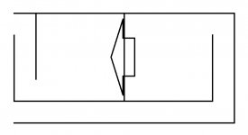
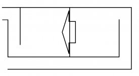
You've come to a really good point. My question is, does the rear chamber which is and should be tuned to the lowest (in the 6th order bandpass theory) need to be larger when the port is longer, in other words, is the port alone not capable of being tuned to the lowest with its length while both chambers are the same in volume, just as the design I sketched here...?
Theres a thing about ‘1/3 vs 2/3’ on one side of the cone and BW vs phase and harmonics.. and it in many wAys extends BW amongst other things a transition between portions of pipes. Offset driver TL is an obvious and often used with a couple descriptions.
But when tuning both sides, it extends into the backwave between them interacting much more than otherwise and at a diffrent phase for the ‘distance traveled from the origin of 180 of eachother. So depending on how you do it, youre playing with 90 degrees one way or the other (inside of 0-90/180/270/360 twice to the Fb of the qw. In 1/4 increments (90degrees if all the same, but can be folded as such too?
This can be broken down into pipe harmonics as they are much the same (coincidentally?) as any rules inside or outside of a box full of sounds. Theres something to it all as it gets closer to the full wave length and size of it. (front loaded real horn). That 1/3-2/3 9offset TL phase thing has shrunk to a point of zero standing waves except the fundamental and its even numbered instead of only odd in a closed end pipe? (I hope thus makes more sense than it sounds, lol).
Im a horrible explainer of much of these things and dont even have the ‘right’ words or descriptions for this but someone can surely do better. Its a long long topic though and hard to ‘teach’ it all in one post i imagine. Its seperate subjects as well, different cabinets and approaches tweeking the vented or not vented sound from each.
Lol!well its really hard to find a driver that appears to be up to the task in a sim. You kinda get stuck with low tuning paths and in qw that designs it sure seems to help if Vas is rather small aside from the motorforce to ‘push all that air. Most of the reason i had to go isobaric one ‘version’ was more motor, less air.
I am honestly cutting it short on the last ‘segment’ and its because I only build what i can sim, otherwise it has no reference to work from and its too hard to keep track of things in the first place!!😀
I think we'd have to invent a specifc driver for a given enclosure design, kinda reverse engineering...

I mean bro, have you really built a sub to that design you drew?
Theres a thing about ‘1/3 vs 2/3’ on one side of the cone and BW vs phase and harmonics.. and it in many wAys extends BW amongst other things a transition between portions of pipes. Offset driver TL is an obvious and often used with a couple descriptions.
But when tuning both sides, it extends into the backwave between them interacting much more than otherwise and at a diffrent phase for the ‘distance traveled from the origin of 180 of eachother. So depending on how you do it, youre playing with 90 degrees one way or the other (inside of 0-90/180/270/360 twice to the Fb of the qw. In 1/4 increments (90degrees if all the same, but can be folded as such too?
This can be broken down into pipe harmonics as they are much the same (coincidentally?) as any rules inside or outside of a box full of sounds. Theres something to it all as it gets closer to the full wave length and size of it. (front loaded real horn). That 1/3-2/3 9offset TL phase thing has shrunk to a point of zero standing waves except the fundamental and its even numbered instead of only odd in a closed end pipe? (I hope thus makes more sense than it sounds, lol).
Im a horrible explainer of much of these things and dont even have the ‘right’ words or descriptions for this but someone can surely do better. Its a long long topic though and hard to ‘teach’ it all in one post i imagine. Its seperate subjects as well, different cabinets and approaches tweeking the vented or not vented sound from each.
Then it'd become more of a TL than a BP, as far as I understood of what's explanated here.
You're gonna be a genius bro, I'm not that intellectual in this subject...

Then it'd become more of a TL than a BP, as far as I understood of what's explanated here.
You're gonna be a genius bro, I'm not that intellectual in this subject...
Im no genius, ive run out of brain in this long ago. Im a part time structural steel fabricator, and an offfroad suspension geek. and a fulltime dumbasss, lol 🙂 Ive been searching for the ‘genius part all over and find it in people here and in FB groups in various ways they approach similar things or share similar forms of the common boundary to sound coming out of a vented box, or not vented
 😱
😱Using qw vs helmholtz, etc doesnt seem to matter(?). Helmholtz spits out at 180 and only in a short window of opportunity...and again (inside)if the frequency being played makes the pressure/velocity swing by the chamber/duct in music?? Short ‘stuffed’ are actually long skinny in reality(?)... i get confused in that, but it seems its the closed end refelction, not actuallly the ‘twice as long’. I dunno, i cant sim all
If tgese things or i could show it?
Bandpass or two conjoined TLs, etc... or a lot more of them, same stuff parallel into series, series the entire way(sortof))...They all need to fit into the overlap and thats a squiggle in response nobody wants to look at.
But im trying to?
One side at a time now,(ive returned to ‘4th order TL’...) and ill force them together.(somehow), as groups after i find the ‘right one’... i hope...
The problem in the past for me was i was using various drivers. Not the same, but the splitting of qw into the 1/3,2/3 on one side or both as seperates remained(in weird ways).
i still jump around in drivers
And yes, i build what ive described, then torn it apart to scavenge parts for the next build. Unfortunate as the more you learm the more you realize you missed in the previous or could have tweeked it just a bit
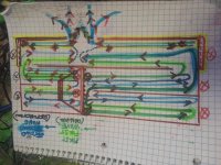
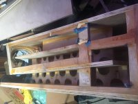
Instill have this one, i gotta cut it open, my dats fell into the vent as did a smart phone recording a slo mo video of tones. This unfinished pic here during covid missing the last ‘ vent ‘ section and abreviated version of it i ‘settled for’ in sim(sim has no folding, i suspect it not telling us the whole story if 180 degree folds are used. This design was followed by others, similar but different sriber so more or less airmass here or there...but im using 180 degree folds now. But it gets too huge.. and i used two drivers...
Attachments

Last edited:
It can get complicated, this is way too excessive and not needed. Nevertheless, it was pretty unique and apparently a great sub. I didnt build it, just gave the ‘ideas’ to a buddy who did and was trying the same types of things in qw enclosures at the time. He understood a lot andi did as well, together we could polish turds🙂 but neither was smart enough to do ‘everything’ or not confuse ourselves trying to, lol!!
Attachments

Youre application of ‘the room’ dimensions inside the box is where i depart from ‘possible’ or, i had to. But i think youre onto something for sure!
I measure all the available spaces i can use and 48” is everywhere in multiples. 8’ x 16, 8x8, or 36” x48” are most common for me(i try all
If this in car sudio and home)
I measure all the available spaces i can use and 48” is everywhere in multiples. 8’ x 16, 8x8, or 36” x48” are most common for me(i try all
If this in car sudio and home)
Its a long long topic though and hard to ‘teach’ it all in one post i imagine.
Indeed! This section and all its links combined with all the other audio related links in the Index does a great job of getting the fundamentals right: HyperPhysics
Bro, this seems to me like a horn+bp+tl kinda, how could you even sim this...? I can't imagine that insane build. Okay, to be honest, I've leart to some extent from a few online resource about some subwoofer enclosures types and their behavior, but haven't dug deep in physics, even my thread title implies I'm not a subwoofer builder, actually I'm not, my subject is computer science though a bass lover.
I'll tell you the real story here, a friend of mine, a subwoofer builder, is excited about my design, but he doesn't know how to sim/mod it, what he really does is (and almost all subwoofer builders in our country) just copying the recognized factory-made subs (most of them are made in your country), so that can never be faulty as the dimensions are original, and he's great at constructing them.
Thus, our country has a great manpower/labour, but what lacks is the engineering skill, that's the common lack in everything in here, that's why we're still a developing country, it's a different story, irrelevant to you, just saying...
BTW, how about the 2 below...?
Attachments
It can get complicated, this is way too excessive and not needed. Nevertheless, it was pretty unique and apparently a great sub. I didnt build it, just gave the ‘ideas’ to a buddy who did and was trying the same types of things in qw enclosures at the time. He understood a lot andi did as well, together we could polish turds🙂 but neither was smart enough to do ‘everything’ or not confuse ourselves trying to, lol!!
My friend too. We're gonna do the same together, something new. But, I really need the simming part to be done by someone knowledgeable. 😕
Youre application of ‘the room’ dimensions inside the box is where i depart from ‘possible’ or, i had to. But i think youre onto something for sure!
I measure all the available spaces i can use and 48” is everywhere in multiples. 8’ x 16, 8x8, or 36” x48” are most common for me(i try all
If this in car sudio and home)
Of course I'm. But that theory, if you read, is "silly" as I titled, just ignore it.

Indeed! This section and all its links combined with all the other audio related links in the Index does a great job of getting the fundamentals right: HyperPhysics
Thanks a lot dude. I really need a physics study.. 🙂
Bro, this seems to me like a horn+bp+tl kinda, how could you even sim this...? I can't imagine that insane build. Okay, to be honest, I've leart to some extent from a few online resource about some subwoofer enclosures types and their behavior, but haven't dug deep in physics, even my thread title implies I'm not a subwoofer builder, actually I'm not, my subject is computer science though a bass lover.
I'll tell you the real story here, a friend of mine, a subwoofer builder, is excited about my design, but he doesn't know how to sim/mod it, what he really does is (and almost all subwoofer builders in our country) just copying the recognized factory-made subs (most of them are made in your country), so that can never be faulty as the dimensions are original, and he's great at constructing them.
Thus, our country has a great manpower/labour, but what lacks is the engineering skill, that's the common lack in everything in here, that's why we're still a developing country, it's a different story, irrelevant to you, just saying...
BTW, how about the 2 below...?
If applied to a length and a driver its easy to sim. Ill gladly help you!! 🙂 thumbs up:
But if you join the exits or seperate them by an infinite length. A sim has you seated a 1 meters distance in a generic boundary thats confusing me more and more because of another reflection..... ‘folding’ is more relevant than ever and quickly the math shows hints if why.
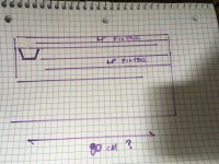
Because of some of this i like to ‘draw’ it(?), cause trig/calculus math was forgotten by me years ago mostly... and my acoustic tech- lingo is kindergarten level🙂
The drawing tells me if everything is 80 cm on the left, the right hand side has an issue if divided by 3 (then its 80/3) instead of two (40 x2) or just as one (80cm x1) alone? Size matters aswell, and a Crossectional area reduction or bulk increase would change this in a sim. It gets quite confusing after that , but ‘folding’ is where i sit and 180 degree folds with a little extra ‘kink’ to ensure they divide the low pass affect or reflected HF material to get absorbed and reflected again in an ingoing cycle of “2” so to speak?
If this makes any sense then im calling the doctor first thing tomorrow! 😀
Attachments
Last edited:
Thanks a lot dude. I really need a physics study.. 🙂
GM is a DIY geeks hero. He has a value as an encyclopedia of resources and facts that is unmatched and greatly appreciated by many many many many!!
Indeed! This section and all its links combined with all the other audio related links in the Index does a great job of getting the fundamentals right: HyperPhysics
Ive been using this for quite awhile. But theres too much to ‘test’ and its all missed and left in the folding(?) not represented in a sim... the last frontier should be obvious. I dunno why its not ‘used’ or ever has been, but i do know my ideas and explanations suck, lol!
Why does no high order cabinet exist thats not split on harmonic lengths as folded, to represent a common Fb and 3Fb ratio? Maybe its the ‘3:1’ that should be ‘2:1’ and 3:1, with a perfect air mass split on each side for a ‘tapped’ driver pushing from the start and mid point? Or the offset in each so we can have our ‘cake and BW too’?? The shape can expand in those segments as needed to fascilitate the driver TS parameters(?) or final impedance at the exit to ambient ‘bubble/bulge/reflection’ end corrected issue? Idunno, but an open end fired into TL, and its basscreflex opposite on the other side of the cone can give the exact opposite results if the ‘TL entry point’ is flipped (closed end driver entry(diret) or far Open end(reflected)what does this mean to us if that is 1/2 the same length and 2/3 the size in volume?
‘ Front’ pipe 200cm2
At 240 cm.(48 liters) is assumed.
Driver entry at open end or closed ^^ swapped to observe the change in results.
Then a ‘rear’ 48 liter chamber with 40 cm dimension. The 200cm2 vent’ required to cancel or not (depending on the driver entry point as noted) is 120cm.
Last edited:
re: those two drawings - they look like regular but low tuned BP6B* to me (*parallel tuned). What am I missing ? (besides brainpower)
Off-Axis 6th Order Parallel Bandpass Enclosure Calculator - DB DYNAMIX AUDIO

Off-Axis 6th Order Parallel Bandpass Enclosure Calculator - DB DYNAMIX AUDIO
Indeed! This section and all its links combined with all the other audio related links in the Index does a great job of getting the fundamentals right: HyperPhysics
It wasnt until i chopped the top panel off this offset driver TL in an effort to create a clear acrylic window on its entire length and segments to look thru and guide the magnet/microphone( inside glass cleaner tool for a fish tank) along its way to find the ‘null’ and at varius frequencies maybe ‘more’ that i realized i had to divide it into equal sections to protect the thin ‘acryillic from flexing. The sections would be wooden windows as a result, but a cross brace in that frame of window pane grid might block my view/access to the actual null or area in question would result. Thats when it became obvious that folding is its own division and exaggeration of the main pipe(2 once the rear section is added to this or removed).
This is just an ‘offset entry Pipe’ with 100cm and 200cm from each ‘end’. The drivers at about 110 if you skew the idea of the tilt required to fit that into the CSA required for ‘Vas and Qts/Fs. with the least ‘stuffing’ (in sim) or similar attempts to control things otherwise..
Attachments
Last edited:
- Home
- Loudspeakers
- Subwoofers
- How silly can this be...?