Hello,
I want to build an ELC84 triode strapped (10mA, 250V) line amp using two CineMag S-217D output transformers with a primary of 12.5K (is that plate to plate impedance or just one plate impedance?).
The ECL84 pentode has an Rp of 3000 Ohms.
Is that a possible application for this output transformer?
I want to build an ELC84 triode strapped (10mA, 250V) line amp using two CineMag S-217D output transformers with a primary of 12.5K (is that plate to plate impedance or just one plate impedance?).
The ECL84 pentode has an Rp of 3000 Ohms.
Is that a possible application for this output transformer?
Attachments
Seems like a poor choice to me, to much power from the pentoded not a great load point . The Excellent ECF80 would be a far more reasonable candidate.
Shoog
Shoog
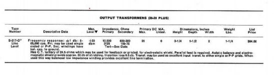
S-217D has 12.5K Ohm plate-to plate impedance, the textbook says. Thats approx. 6K for one tube.
<In a push-pull transformer, operating in class AB, the loadline is not a straight line. While both vacuum tubes are conducting, the impedance seen at the anode is half than that of the entire transformer. When one of the two vacuum tubes quits conducting, just half transformer is used, and given that the impedance goes with the square of the turn ratio, the impedance will be one fourth of the entire transformer impedance.>
ECL84 triode strapped is 3K Ohm, thats exactly one fourth of the whole transformer impedance.
I have six of those EL84 and would like this to work out, no ECF80 please.
Last edited:
As is typical in these situations, you can do what you like, but its my opinion that such a project is a waste of precious ECL84's and the transformers when applied to a line amp.
IMO its just an all round poor idea.
You can achieve a powerful step down transformer loaded line amp using 5687's which will probably better what you are attempting.
Shoog
IMO its just an all round poor idea.
You can achieve a powerful step down transformer loaded line amp using 5687's which will probably better what you are attempting.
Shoog
Last edited:
5687 at 250V, 12mA has plate impedance of 3k Ohm.
Why do you prefer 5687 over ECL84 (its comparable to a hotter ECC88) at this place?
ECL has 3K Ohm at 235V, 20mA.
It could be done with just two ECL tubes per channel instead of a separate line amp/ phase splitter tube.
Why do you prefer 5687 over ECL84 (its comparable to a hotter ECC88) at this place?
ECL has 3K Ohm at 235V, 20mA.
It could be done with just two ECL tubes per channel instead of a separate line amp/ phase splitter tube.
Last edited:
This is a full function tube pre, including phono. Two ECL could form a complete line PP-section.
Whats the use of a line amp?
Short answer: level attenuation and powerfull sound. And it has 600 Ohm balanced output.
Whats the use of a line amp?
Short answer: level attenuation and powerfull sound. And it has 600 Ohm balanced output.
Which a 5687 can do better. I have done it with a 5687 and it produces some ludicrous amount of output ampage. You simply do not need to throw a triode strapped EL84 at the job - its a waste.
What I am saying is its your choice to apply the wrong valve to the intended job, but I just wanted to point out that there are far more appropriate candidates. The ECL84 is now a very rare valve and there are plenty of appropriate uses for it.
Shoog
What I am saying is its your choice to apply the wrong valve to the intended job, but I just wanted to point out that there are far more appropriate candidates. The ECL84 is now a very rare valve and there are plenty of appropriate uses for it.
Shoog
OK, understood and appreciated your testimonial. What output transformer did you use, please?
P. S. 5687 NOS is, for whatever reason, much more expensive. Maybe its a desirable tube for some kind of audio gear?
P. S. 5687 NOS is, for whatever reason, much more expensive. Maybe its a desirable tube for some kind of audio gear?
Last edited:
This is a full function tube pre, including phono. Two ECL could form a complete line PP-section.
Whats the use of a line amp?
Short answer: level attenuation and powerfull sound. And it has 600 Ohm balanced output.
The phono preamp makes sense when you wish to listen to LP's.
For the rest a separate line level amp is a waste.
With non-phono sources (DAC) you have low output impedances already, enough to "drive" an attenuator of whatever type.
IMO it makes more sense to create a 1 VRMS sensitive power amp.
What exactly you mean with "powerfull sound"? 😡
600 ohm balanced output is a studio reference, not necessary for home audio.
Just some one's I had lying around.OK, understood and appreciated your testimonial. What output transformer did you use, please?
P. S. 5687 NOS is, for whatever reason, much more expensive. Maybe its a desirable tube for some kind of audio gear?
The 5687 is an excellent valve but as you say is quite popular for that reason.
My favourite SLCF pre-amp is based upon the rather excellent ECF80.
As has been pointed out a line stage needs no gain these days so matching the step up of your "triode" to the step down of your transformer is the best way to get to a "high drive" line stage without excessive gain which then needs attenuation with voltage dividers. Excessive gain is almost always the issue with preamplifers these days.
A phono preamp is a specialist application needing specialist valves so its best to choose the appropriate valve for the role rather than attempting to shoehorn a spare triode into the roll.
Shoog
OK, just found two ECF80 in the archive ;-)
Did you triode strapped the pentode? Unfortunately, I cant find loadlines for this.
What OP point would you choose, pentode or triode mode, for that transformer, please?
Did you triode strapped the pentode? Unfortunately, I cant find loadlines for this.
What OP point would you choose, pentode or triode mode, for that transformer, please?
I triode strapped mine but I then cap coupled it to the output . would have to trace the circuit to tell you much more..
The data sheets are the goto place for best operating points, the fun is in finding the right valve for your intended purpose.
Shoog
The data sheets are the goto place for best operating points, the fun is in finding the right valve for your intended purpose.
Shoog
No I did a fully balanced 5687 preamp with a Garter bias to ensure matched standing current in the PP pair. Has an input transformer for initial phase splitting followed by the 5687 and then a PP OT. This technique means that each channel needs a stereo pot for volume control for which I used a four gang wire wound linear pot (heliostat) for both channels.
The Super Linear Cathode Follower using the ECF80's is a different beast which simply has output caps. The beauty of the ECF80 is that both the Triode and the Pentode pass the same current so can be used in stacks as active load and sinks. This was always the better of the two approaches as there is less complexity in dealing with ringing produced by transformer parasitic. Transformers like to have a fixed and predictable source and load impedance otherwise they ring like hell. This requires careful attention to parallel loads or zobel networks to tame and without good equipment its challenging to get right. The better the quality of the transformer the harder it is to load correctly.
Here is my opinion on transformers, which I have used a lot, its much more difficult to get good results using small signal transformers than simple capacitors - because they require far more skill in tuning. Also most of the negative things attributed to capacitors in coupling are a direct consequence of poor circuit design - to whit I mean to high output impedance in the driving circuit and the first cousin of to low a driving current. Drive a capacitor hard and it will outperform a transformer every day of the week.
Again, these are just my opinions which you are free to ignore.
Shoog
Last edited:
Shoog,
very interesting read.
In a different thread, you wrote about this special cathode follower:
<ECF80 makes an excellent audio tube. I have one setup as a Super Linear Cathode follower with two making up each channel. The Triode and pentode can pass just about the same current so this makes them excellent for stacked topology.
The way mine works are :
Triode of first tube as first stage voltage amplifier.
Pentode of the first tube as bottom of "totem pole CCS", second valve with triode as cathode follower loaded on the CCS and finally the pentode triode strapped as the voltage follower on top.
Literally the best thing I've ever built and copes with ridiculously high voltages.>
Which design topology do you mean with "totem pole CCS", please? I could not find anything about it.
So you stack a triode as cathode follower above a "totem pole CCS" and then, the third element, a pentode (triode strapped) as "voltage follower" on top of it.
How should this work out, please? The only thing I can imagine is a cathode follower with a tube constant current sink. Why is there a "voltage follower" on top of it? What do you mean with a voltage follower circuit? Whats its use in this circuit?
Could you please clarify (maybe with a schemo).
Many thanks in advance!
Last edited:
You got the order wrong:
Triode first stage into
pentode on bottom as CCSink - on top of this is a triode Cathode follower - the final Pentode is triode strapped and acts as a Constant Voltage load onto the Cathode follower.
The philosophy behind this is that a triode works most linearly at a constant current and the voltage follower acts to ensure that the voltage on the plate of the cathode follower is at a constant voltage. You are removing two of the potential sources of distortion.
This is not my idea as it was championed by Allen Wright - who in turn borrowed it from Hewlett Packard. Look at the second stage of this circuit to see how it looks in a pure triode form:
https://soundmovements.co.uk/diyaudio/FVP5a.gif
Notice the 2K2 cathode resistor on the bottom which is amplified by the mu of the triode CCS. A pentode has many times the mu of a triode so it multiplies the impedance of the CCS many times what is possible with the triode. It was a purist thing to use a triode - but it was a poor choice which doesn't have to be followed if you have a pentode available.
Shoog
Last edited:
Thanks for the explanation, Shoog.
For what purpose the cathode follower needs a "constant voltage load", as it has a constant high B+ potential anyway? Does it optimize the power supply for the cathode follower? I once learned, constant voltages need high impedances, but does this top-tube optimize this?
Very interesting circuit ideas to optimize the cathode follower.
Last edited:
Its what's known as a bootstrap arrangement. All I can say is it produces noticeably lower distortion - enough for HP to consider spending extra cash on.
I built three different versions of this circuit with the last one built with jfet input and MOSFET second stage - it now my main preamp and the closest thing to wire with gain I have heard.
Shoog
I built three different versions of this circuit with the last one built with jfet input and MOSFET second stage - it now my main preamp and the closest thing to wire with gain I have heard.
Shoog
Last edited:
- Home
- Amplifiers
- Tubes / Valves
- ECL84 triode strapped push pull line amp