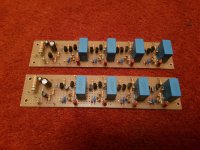
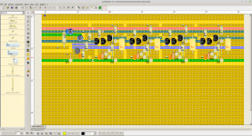
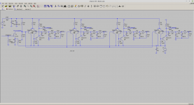
Schematics of 4 channel servo bias board for KT88/6550 PP output stages. C7 should be a good quality cap such as film and is 100V. C8 is low voltage 10uF ceramic. POWERUP should be a 0V for 25s or so until the cathode emission starts and then pulled to -10v or greater to make the bias active. R34/R33 sets the bias current in this case 36ma or so. Transistors 100-120V PNP good Hfe.
Enjoy.


Enjoy.


Last edited:
Very cool man!
How can it be made to work with larger voltages like when running in triode? Say a bias voltage of -170V that will automagically adjust for current of 120mA per tube?
How can it be made to work with larger voltages like when running in triode? Say a bias voltage of -170V that will automagically adjust for current of 120mA per tube?
That "POWERUP" signal is a good idea. Without it the bias voltage keeps rising (becomes less negative) trying to increase current while the tubes are cold and current is zero. Then when the tubes warm up the current rises fast and the servo has to try and catch up. Since servos have to be slow to avoid responding to audio signals you can end up with significant overshoot. Probably not so bad with tubes, but I've done the same thing with a hybrid mosfet output stage - they are much less forgiving 😀
Reducing the 10R cathode resistor will set the current.
Current = .36 / R.
As for the voltage, I think it will with higher voltage PNP's. I would put one channel on LT spice and the valve of your choice.
You may be able to get away with 2u2 film at 200V rather than 4u7.
Current = .36 / R.
As for the voltage, I think it will with higher voltage PNP's. I would put one channel on LT spice and the valve of your choice.
You may be able to get away with 2u2 film at 200V rather than 4u7.
Being a push-pull amplifier what is doing when output power rises and naturally current through resistors ? 😀
That current is not AC but DC so can't be filtered .
That current is not AC but DC so can't be filtered .
OK so when the amp is in the class A part of the AB all is good. However with a large sine wave signal the average filtered DC does go up. This will cause the bias to reduce. Its not as bad as cathode bias however. The trick is the diode D4. This starts to conduct and reduces the peaks so that the bias does not drift down as much. The circuit can still be defected by very large asymmetric signals over a period of time - but that is not what real audio does.
The circuit also limits the maximum grid voltage that can be applied. In this case about -34V. It also has good power supply rejection of the negative rail.
I've built them before and are happy with the performance.
The circuit also limits the maximum grid voltage that can be applied. In this case about -34V. It also has good power supply rejection of the negative rail.
I've built them before and are happy with the performance.
Last edited:
If you are fussy, the bias can be monitored while running class AB at high power, and the value of R21 (1k) that feeds D4 can be tweaked to minimise the bias drift (changes the current through D4 and hence slightly changes the voltage across it). I've done this, the optimum value changes a bit depending on signal level but a good compromise can be found. Or as baudouin0 says, real music isn't like that so probably not worth the bother.
Only I don't have anything in between. I just have a regulated HT rail. It only needs about 3ma. of course you can change the 68k resistor at the input.
Last edited:
I've been looking at this myself - for me the grid is grounded, the cathodes are boosted to +30V. Then soft start begins and at 10-30 seconds the B+ is at full voltage, the startup bias is then switched out and the tubes will pass current. That way there's no stray capacitances or signal paths. I should add both pre-input and outputs are switched out on the B+ startup and the tube sections are common cathode.
After start the grid bias is then set by cathode fixed bias.
After start the grid bias is then set by cathode fixed bias.
Last edited:
- Home
- Amplifiers
- Tubes / Valves
- Servo Bias Schematics
![2021-01-29 09_59_13-LTspice XVII - [bias300.asc].png 2021-01-29 09_59_13-LTspice XVII - [bias300.asc].png](https://www.diyaudio.com/community/data/attachments/837/837485-81ac1c8ff3db27cb9f690a8ef1da0c6f.jpg?hash=gawcj_PbJ8)
