Math is correct but the K voltage will rise in conjunction with the increase in resistor ohm value.So you have to remeasure the K voltage again after you change the resistor and recalculate.
Also your B+ might rise due to the lessening of current through the resistance inherent to the power supply (transformer wiring impedance ).
Understood. Thank you. The mistake I always seem to be making is not considering how one component change can affect the entire circuit rather than just the area my brain is focused on.
Best to get a few different values of R so I can adjust again if necessary.
The schematic says B+ of 400v and you have 426v. Then assuming your mains are 120VAC:
400/426*120VAC = 113VAC (about).
I wonder if you have a 115V power transformer. If you have AC heaters check to see if they are close to 6.3v. That would give you an indication.
This was my guess too (115V primary). The power tubes are AC heated (drivers and P/Is are DC) and the wiring is obvious so I can check to see what the 6.3VAC tap is at.
Just curious. Do you know the Ra-a of your output transformer?
May be good to know when adjusting the operating point with better sound quality in mind.
Unfortunately the OPT primary impedance is not indicated. I've just read a couple of websites and watched a video on how to determine the turns ratio and calculate the primary impedance. Will do that some time this weekend.
cnau,
Confirmed heaters are getting 6.5-6.6VAC so the math says PT primary is somewhere between 114.5VAC-116VAC. So ya.
Will probably wait till tomorrow to figure out OPT primary impedance.
Confirmed heaters are getting 6.5-6.6VAC so the math says PT primary is somewhere between 114.5VAC-116VAC. So ya.
Will probably wait till tomorrow to figure out OPT primary impedance.
Thinking more about the power supply now. As you can see in the schematic, the B+ power section is a bit of a joke. I've modeled it in PSUD2 (also attached) and it shows a full 3.15V of ripple.
Since any filter I implement is going to change B+, I think it might be wise to take that into consideration before finalizing any values for the 4 Rk.
I don't really have room in the chassis for a choke, so I am thinking of just tagging a C-R on in front of the existing 470uF cap, to make a C-R-C. PSUD2 says 470uF-100ohm-470uF would reduce ripple to 66mV and B+ would drop to 406V.
Attachments
Does it make any difference not having the grid stopper 1k resistors on the pin for the grid, after the grid his resistor? Or is it just the way the schematic was drawn?
Ideally the grid stopper resisters should be right on the tube socket. But aside from running hot the amp appears to be stable, so leave the grid wiring as is.
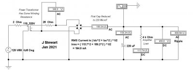
The PT is running into a full bridge of silicon diodes driving 470 microF. Your amp is setup for cathode bias, the load peak currents will not deviate too far from average as they would be running fixed bias. The 470 microF cap could be safely reduced to say 200 microF, that will relieve some of the heating in the PT. It is the RMS current in the PT that causes the heat, not the average current. High RMS currents are caused by continuous large current peas in the rectifier circuit. You will see a small drop in the B+ voltage.
The individual cathode caps should be 1/2 the capacity of the original hookup. Hard to believe but they are part of the negative feedback network that maintains the amplifier stability. Again difficult for many to believe, to calculate the bias resisters for a pentode output section, the pentode is treated as a triode because it is at DC were the correct bias needs to be set. Separate bias resisters will help overall DC stability.
Your power supply simulation software does not shew any allowance for source impedance / resistance as seen by the rectifier bridge. That means that the computed ripple is the max possible. The final value of ripple & RMS current is very dependent on the power transformer winding AC resistance & leakage reactance, your actual ripple will be less than computed in the final circuit. That is a good sign.🙂
The individual cathode caps should be 1/2 the capacity of the original hookup. Hard to believe but they are part of the negative feedback network that maintains the amplifier stability.
Didn't realize a difference of 1.4 Hz was that critical. Good to know.
With cap tolerances all over the place( a 100µF capacitor with a ±20% tolerance could legitimately vary from 80μF to 120μF and still remain within tolerance) should we be measuring them before using them in that application?
At what point does it become a problem?
Thanks.
Ideally the grid stopper resisters should be right on the tube socket. But aside from running hot the amp appears to be stable, so leave the grid wiring as is.
The PT is running into a full bridge of silicon diodes driving 470 microF. Your amp is setup for cathode bias, the load peak currents will not deviate too far from average as they would be running fixed bias. The 470 microF cap could be safely reduced to say 200 microF, that will relieve some of the heating in the PT. It is the RMS current in the PT that causes the heat, not the average current. High RMS currents are caused by continuous large current peas in the rectifier circuit. You will see a small drop in the B+ voltage.
The individual cathode caps should be 1/2 the capacity of the original hookup. Hard to believe but they are part of the negative feedback network that maintains the amplifier stability. Again difficult for many to believe, to calculate the bias resisters for a pentode output section, the pentode is treated as a triode because it is at DC were the correct bias needs to be set. Separate bias resisters will help overall DC stability.
Thanks for this! I understand most of it and will take your advice. One question though - If I want to implement a CRC filter but also reduce the 470uF cap to 200ish, should I build a CRC of 220uF-100R-220uF ? Or, would something else be better?
Your power supply simulation software does not shew any allowance for source impedance / resistance as seen by the rectifier bridge. That means that the computed ripple is the max possible. The final value of ripple & RMS current is very dependent on the power transformer winding AC resistance & leakage reactance, your actual ripple will be less than computed in the final circuit. That is a good sign.🙂
The software actually does have allowance for source impedance. I am in the process now of taking resistance measurements of the PT primary winding and HV winding and measuring off-load voltage so I can be sure to enter the correct values, to obtain a more accurate simulation. More on this later.
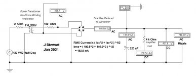
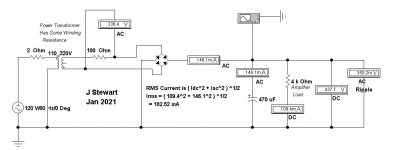
The RMS current is the sum of the squares of the AC & DC currents, than the Square Root is taken. So in Solution A where there is no PT winding Resistance, the RMS current is about 60% greater than the load current. That is typical of capacitor input filter type circuits.
Let me know those winding resistances, they can easily be stuffed into the simulation.
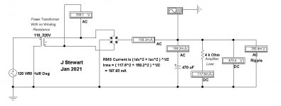
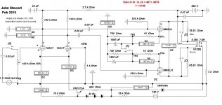
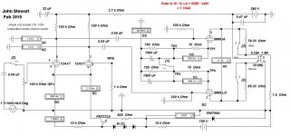
In Solution B typical values of DC resistance of the windings have been stuffed in, the RMS current has been reduced. In Solution C a 220 microF first cap has been plugged in where the 470 microF had been. The change is very small, the transformer winding resistances dominate the solution.
Somebody please check my numbers.
I'll comment on NFB later,🙂
Let me know those winding resistances, they can easily be stuffed into the simulation.
In Solution B typical values of DC resistance of the windings have been stuffed in, the RMS current has been reduced. In Solution C a 220 microF first cap has been plugged in where the 470 microF had been. The change is very small, the transformer winding resistances dominate the solution.
Somebody please check my numbers.
I'll comment on NFB later,🙂
Attachments
Thanks again for your help.
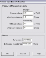
PT primary winding = 1.9 ohms
PT HV secondary winding = 26 ohms
PT HV secondary off-load voltage (disconnected from the bridge) = 347V
(120VAC input on the primary)
I've attached the transformer configuration I am now using in PSUDII.
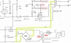
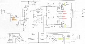
I should note that the power section I showed before was incomplete. I thought the rest wasn't important, but I am slowly learning that "everything affects everything" so here I have also attached the complete high voltage section. Actually, this is basically the whole schematic now. I should also re-iterate something I mentioned earlier - that I converted the output to triode mode. That is also reflected on the attached schematic. Yellow highlights show existing state, pink highlights indicate proposed changes to Rk and bypass caps (vs. existing common configuration).
Perhaps best to leave the power supply section alone for now?
PT primary winding = 1.9 ohms
PT HV secondary winding = 26 ohms
PT HV secondary off-load voltage (disconnected from the bridge) = 347V
(120VAC input on the primary)
I've attached the transformer configuration I am now using in PSUDII.
I should note that the power section I showed before was incomplete. I thought the rest wasn't important, but I am slowly learning that "everything affects everything" so here I have also attached the complete high voltage section. Actually, this is basically the whole schematic now. I should also re-iterate something I mentioned earlier - that I converted the output to triode mode. That is also reflected on the attached schematic. Yellow highlights show existing state, pink highlights indicate proposed changes to Rk and bypass caps (vs. existing common configuration).
Perhaps best to leave the power supply section alone for now?
Attachments
Last edited:
In my experience, a common cathode resistor along with its capacitor is a better option to PP amps.
It's more self-balancing in operation, and better nullifies any potential hum.
It's more self-balancing in operation, and better nullifies any potential hum.
This seems to be a matter of debate then, because I have read that the common cathode resistor topology assumes closely matched tubes. If not, one tube in the pair can start drawing most of the current and eventually go into runaway and fry itself. This is exacerbated if the tubes are biased close to or past their max dissipation already (which they certainly are in this case).
This post in particular sounds like it makes a hell of a lot of sense. Push-Pull Cathode Bias Resistors
This post in particular sounds like it makes a hell of a lot of sense. Push-Pull Cathode Bias Resistors
Last edited:
Honestly, I've never seen the "runaway tube" issue in a properly designed PP amp.
But, alas, I'm sure there are individuals out there with worries and self-made conclusions.
But, alas, I'm sure there are individuals out there with worries and self-made conclusions.
Here are two simulations using the actual DC winding resistances. One shews the results with a 470 microF first cap, the other while the first cap is set lower at 220 microF.
The actual AC winding resistances are greater, caused by skin effect & proximity effects. The rectifying action creates large amplitude odd order harmonic currents in the windings. The increase in AC resistance is caused not only by the fundamental power frequency but all those harmonics as well. Something for the transformer designers to worry about.
Either way you may find you need more filtering, triode connected tubes are more susceptible to PS hum tan either UL or pentode connexions.
I've got some worked examples somewhere in my file, if I can't find them I'll do another set later.🙂
Attachments

Why Separate Cathode Resisters
About 20 yrs ago I watched as a 6080 cooked thru one of the control grids while using a common bias resister. I was in the middle of another of those 'Proof of Concept' experiments, a different way to drive a low mu triode.
More recently & for a different reason I bench tested several common twin triodes for use as PP Audio Amps. I tried 6SN7, 6BX7, 6BL7 & 5998. All have the same pinout, how convenient is that?🙂
So in Class A & inside the dissipation limits the 6SN7 managed One Watt, the 6BX7 & 6BL7 3W & the 5998 10W. The results data includes measurements of THD & Harmonics at several different levels. All the test data was put on DIY about two years ago.
While running the tests I set up a way of unhooking common bias & applying separate bias resistors. Did this while the 5998 was in the socket. The separate bias scheme was by far better. Results are attached.🙂
More later.
Attachments

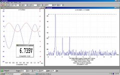
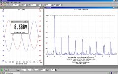
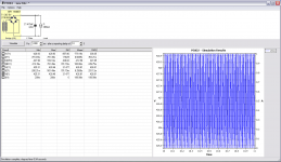
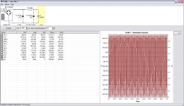
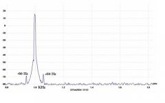
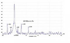
PS Ripple Causes Sidebands on Program Material
Here are a couple of spectrums showing PS Ripple Sidebands on program material. One with the CLC filter in the cct while the other is with the L shorted. The output is set at 2.5 Watts.
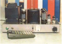
The amplifier is PPUL 6L6GCs, something I built two of around 1960. The CLC is 40 microF, 1.5H, 35 microF. The L is a Hammond 156R, small enough to fit inside the chassis. The B+ runs around 445V, thru a 5V4GA, but it was originally built for a 5AR4. The PT is a Hammond 273BZ. I have used SS octal rectifiers in this one with good results.
The amp is nominally 25 Watts.
The Spec A used was a Pico Technolgy 16-bit ADC-216, so 96 db dynamic range is possible with care.🙂
Here are a couple of spectrums showing PS Ripple Sidebands on program material. One with the CLC filter in the cct while the other is with the L shorted. The output is set at 2.5 Watts.
The amplifier is PPUL 6L6GCs, something I built two of around 1960. The CLC is 40 microF, 1.5H, 35 microF. The L is a Hammond 156R, small enough to fit inside the chassis. The B+ runs around 445V, thru a 5V4GA, but it was originally built for a 5AR4. The PT is a Hammond 273BZ. I have used SS octal rectifiers in this one with good results.
The amp is nominally 25 Watts.
The Spec A used was a Pico Technolgy 16-bit ADC-216, so 96 db dynamic range is possible with care.🙂
Attachments
Suseptability of Triodes to PS Ripple
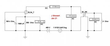
Because their rp is less than the load Rl, any power supply ripple will occur across the load. The example is simulated for a triode connected EL34.
The PP Connexion can cancel much of that but is never perfect as seen in the previous post.
A One volt interfering signal has been inserted into the B+ lead, 3/4 volt appears across the OPT since it is set for 3K while the triode connected EL34 rp is about One K.
A pentode is usually loaded with an Rl much less than the pentode rp, the resulting ripple has much less effect on the output signal.
The UL connexion is somewhere in between dependent on the UL %.🙂
Attachments
As much as I appreciate your help, and enjoy trying to learn about it all, I am feeling overwhelmed. I am a novice (at best), so your examples are quite difficult for me to understand.
Since I don't have room for a choke in the chassis (nor on top) my only option to clean up the power supply (and drop B+ a bit) is to go with a C-R-C, so I want to try to focus on what components I should use to accomplish that. If I can use the 470uF cap that is there now, that would be nice. Perhaps I could go with 47uF-100ohm-470uF? B+ would drop about 30 volts in this case.
I am guessing I would need to revisit my cathode bias resistor plan if I make this change to the power supply - but that is just a guess because I don't know what I am doing.
My overall goals are:
1) reduce PT load/stress/heat
2) reduce dissipation on the EL34 tubes to ~20 watts each
3) maintain stability (improve it, actually)
If I am simply much better off to re-wire for UL mode (with those goals in mind) then I am fine with that but if it is possible then I'd like to keep triode mode (with NFB as it is).
Last edited:
- Home
- Amplifiers
- Tubes / Valves
- P-P EL34 Modification