I have read 3 different websites on how to build a simple voltage divider. I get the theory. It all makes sense. Dropping from 24V down to 12V I use two resistors of equal value. The circuit makes sense and is easy to build.
However, none of the sites provide any information on what the actual component values should be, or what wattage they should be.
In other words if I want to split 24V down to 12V, based on the sites I have read I can do it with a pair of 2ohm 10 watt resistors, or with a pair of 20kohm 1/4watt resistors.
Either way I get my 12V, but there has to be a lot more to it than this.
Can someone shed some light on how the resistor values and wattage ratings should be selected?
Voltage divider is mainly for low current applications. The example using 2 equal resistors to get half the voltage is only true until you draw any current from it.
The load also has a resistance (V/I=R). This is in parallel with the second resistance and therefore forms part of the second resistor.
Work out a few real life examples eg 12V bulb from 24V supply to see how it works. Your 12V bulb would be resistor 2 and resistor 1 would have the same value as the resistance of the bulb.
Typically, a voltage divider would be used for biasing a transistor and would be based on passing say 10x the bias current to maintain a reasonable accuracy.
For high power applications such as the bulb example it is simply too wasteful of power, for a 10W bulb you would waste 10W in the resistor.
I'm sure someone will correct me if I've got it wrong.
I don't think I'd build that 2 ohms circuit! You'd have 24 volts across 4 ohms. Power is E^2/R so 576/4 or 144 watts, 72 watts dissipation for each resistor. 10 watt resistors would go up in flames very quickly.
So, the two big things to think about would be 1) how much power am I willing to waste in the divider? 2) What's the load on the divider? If the load is much, the ratio will be thrown off. For most things you might use a factor of 10-20 or more in the divider, compared to the load. For precision metrology applications it would be more like 100,000 to more than a million, to prevent even tiny errors.
I find a spreadsheet is handy to get a feel for things, even as simple as a divider circuit. Start with the easy part. Enter values for the voltage and the resistors. Calculate the current through them, the total power and the power for each one. Add the load as another resistor across the bottom one. Do the parallel combination and redo the current and power numbers. It's great practice and you can apply what you learn to other circuits.
Last edited:
Thanks russc.
Perhaps it will help if I get into the specifics.
I'm building an amp with a 24V 4.5A SMPS. The amp will use the full 24V at about 3A max.
However, I want to install active cooling (let's not debate how idiotic this may seem 🙂 ) and I'd like to use 12V fans and a 12V PWM fan speed controller. The current draw of the controller and fans will be very low (MAX 400mA - probably more like 100mA). It seems stupid to install a separate 12V supply for the fans if I can just build a voltage divider to feed the fan controller.
Last edited:
Sorry, I was typing as you were, Conrad. I will have to consider all that and do some thinking/learning.
Can you use 2 fans in series to suit 24V supply?
Alternatively, use a DC-DC converter, cheap and efficient.
LM2596 DC-DC Adjustable Power Supply Step Down Module Buck Converter 3V-35V | eBay
Alternatively, use a DC-DC converter, cheap and efficient.
LM2596 DC-DC Adjustable Power Supply Step Down Module Buck Converter 3V-35V | eBay
24 volts and with an amplifier pulling 3A.
I would say a linear 12 volt reg would be a good option. At 100ma you are only adding 1.2W dissipation to your overall total which in the scheme of things... isn't very much 🙂
I would say a linear 12 volt reg would be a good option. At 100ma you are only adding 1.2W dissipation to your overall total which in the scheme of things... isn't very much 🙂
One can drive 12 volt fans by PWMing a 24 volt supply, but the controller has to have some way to limit the output. That way you'd need nothing else, but I don't know if such a controller is available off-the-shelf. All the other solutions given seem good too.
Thanks everyone. I can see now that a 7812 makes a heck of a lot of sense in this case, rather than dicking around with a voltage divider.
I thought I might be able to learn something by trying to build one - and I did already learn a lot from your responses so that's great.
I thought I might be able to learn something by trying to build one - and I did already learn a lot from your responses so that's great.
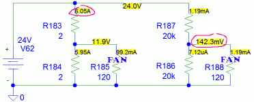
....I can do it with a pair of 2ohm 10 watt resistors, or with a pair of 20kohm 1/4watt resistors....
As said: do the math.
First: you MUST include the load as part of the divider!!
A 12V 0.1A fan is conceptually 120 Ohms. Maybe not, but close enough to be instructive.
Your two 2r still give 11.9 Volts, but the scheme sucks a LOT of power! All as waste heat.
Your two 20k are thrifty but only put 0.14V to the fan (won't spin).
For many fans, a workable fix is ONE 100r resistor series. The fan is the whole other half of the divider. However fans are not resistors and there can be some unexpected even unhappy side effects of a motor in a high resistance circuit.
Attachments
There are eist 24VDC coolers too, but the variety of them iw not very large. So they can be too noisy (industrial type).
- Home
- Amplifiers
- Power Supplies
- Voltage Divider Component Selection