Hi!
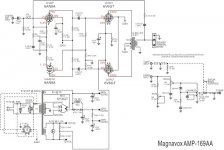
Can anyone help with Magnavox Amp 169 AA or Magnavox Amp 169 BB schematic.
Tubes used: 6AN8 (pre and split) - 6V6GT X2 (push-pull output) - 5Y3GT (rectifier)
I've got a Magnavox AMP 169 AA that I am planning to rebuild.
Could only find in poor resolution, many values are unreadable (
Thank in advance !)
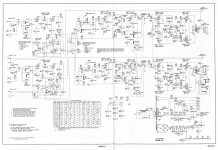
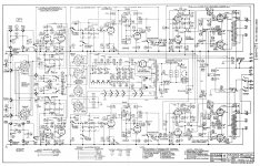
Attachments

It's Fantastic !!!!! Koonw ! You are Real Santa Claus !!!)
Thanks a LOT !!!!!!
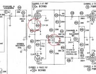
Don't forget to add the (missing) cross connection dot between the 20uf preamp stage cathode bypass and .22uf filter stub. else your preamp/driver tube will be floating without power.
!! Don't forget to add the (missing) cross connection !!
Ha !)
I broke my brain ) analyzing the feedback loop!
Just a lost point)
And without it, the cathodes hang in the air )
But the main question I have is regarding phase inverter:
What is advantage of such a topology )
We can use 6AN8 triode as conventional phase splitter ( with equal R in anode and cathode circuit )
What's the trick here?)
The feedback loop is also upset )
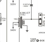
Resistor 68 ohm and capacitor 0.22 uf increase gain from aprox 10600 Hz
i think to compensate high frequency losses in a weak output transformer)
nevertheless the amplifier sounds very good)
I was very surprised by the quad capacitor 10+20+30+40 uF / 450V
Are anyone produces such caps now? )
Ha !)
I broke my brain ) analyzing the feedback loop!
Just a lost point)
And without it, the cathodes hang in the air )
But the main question I have is regarding phase inverter:
What is advantage of such a topology )
We can use 6AN8 triode as conventional phase splitter ( with equal R in anode and cathode circuit )
What's the trick here?)
The feedback loop is also upset )
Resistor 68 ohm and capacitor 0.22 uf increase gain from aprox 10600 Hz
i think to compensate high frequency losses in a weak output transformer)
nevertheless the amplifier sounds very good)
I was very surprised by the quad capacitor 10+20+30+40 uF / 450V
Are anyone produces such caps now? )
The idea and driving force behind the special and unique phase inverter is:
1. An Inverter that has the gain of a pentode.
2. The circuit will work with a triode for the inverted signal.
3. Both the pentode and triode are in one tube.
Only 1 socket required.
# 1 and # 3 are the real reasons.
(A dual triode inverter would not have the gain).
Other than that, there is no advantage.
This special circuit gives gain, and saves production costs.
No lower distortion.
No wider frequency response.
...regarding phase inverter:
What is advantage of such a topology )....
It is better if cathodes are NOT a hundred volts above ground.
Yes, by the 1940s this was usually acceptable; still it stresses the cathode insulation.
" It is better if cathodes are NOT a hundred volts above ground "
I think it's THE BEST reason !
Scott in 299 model use variable resistor R5 for Split adjustment and this is very rightly)
And the feedback circuit is linear) which indicates a higher quality of the output transformer)
And what about quad capacitor 10+20+30+40 uF / 450V
Are something similar available on the market now ?)
I could find only double )
[ CBB65 Motor Run Capacitors (Round-Shaped, Dual Capacitance Value) ]
Attachments
Just for fun I was trying to reproduce that circuit in LTSpice. There is no way in hell the 6AN8 spice model can reproduce these operating conditions, let alone the voltages noted in that Korean site. Real life tube (specially small signal pentodes) can behave in a much different way than a math model, I guess
Last edited:
6AN8 is very interesting lamp I think)
But you're right) LTSpice will not reveal its secrets and charms)
they must be looked in practice )))
StillI have't measured the operating voltage of the amplifier and tubes )
Just listen it and enjoy))
Can't understand how it sounds so great with such a small output transformer )))
Yesterday got idea to make a copy of this amp))
Are anyone disassemble it's output transformer ?
What's with the sections of primary and secondary windings ?
I think it's very simple
W1-W2-W1 at best: W2-W1-W2-W1-W2
According to the scheme:
Raa=6800 Ohm RW11=135 Ohm RW12= 140 Ohm
According to measurements ):
Core look like EI 60 with thick 20 mm ( 0,787402 " for american friends ))
Any ideas ?)
Attachments
"The 4k7 Ohm/ 47nF bass boost in the loop feedback is the secret sauce"
Exactly!)))
And
The 68 Ohm/ 0,22 uF treble boost in the loop feedback is the another one )))
50 cents And no problem))
Study! Luxman Sansui and Tango engineers ))))))
Exactly!)))
And
The 68 Ohm/ 0,22 uF treble boost in the loop feedback is the another one )))
50 cents And no problem))
Study! Luxman Sansui and Tango engineers ))))))
Being that this amplifier was developed to drive an open back cabinet console type,
I thought the fixed eq vas there for this very reason
I thought the fixed eq vas there for this very reason
The output transformer of this amplifier has primary inductance of 37 H. About -3 dB at 50 Hz small signal with PP 6V6 plain output stage. At full power, likely saturation distortion at this frequency.
This was adequate for 12" Magnavox speakers this amp was designed for. Their lower frequency is about 70 Hz.
This was adequate for 12" Magnavox speakers this amp was designed for. Their lower frequency is about 70 Hz.
Last edited:
The windings of this transformer are not sectioned, just secondary on top of primary. However, high frequency response extends to 10-12 K. Small compact winding accounts for relatively good HF performance without interleaving. Magnavox console has 2-way speaker with 12" main driver and 4" paper cone tweeter.
- Home
- Amplifiers
- Tubes / Valves
- Magnavox Amp 169 AA schematic