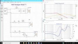
OK, after MANY hours tracing and retracing the connections on a pair of 1983 Paradigm Model 11 3-ways, predicated by replacing broken posts, this seems odd.... These are the two possible ways this was assembled (when I got it) and assume this is the OEM.
The tweeter had spade terms crushed onto the solid component wires and I didn't make note of the polarity, but no matter how I look at it, this crossover doesn't seem right. I did not rewire anything, just replaced the posts.
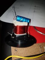
The tweeter has the cap and coil attached, plus all the board mounted bits.
The mid appears first order band passed and attenuated, the tweeter appears to be maybe third order and attenuated, and the woofer is a second order. I assume the mid should be wired out of phase?
The freq graph should be.... better.....
Any insights are greatly appreciated.
The tweeter had spade terms crushed onto the solid component wires and I didn't make note of the polarity, but no matter how I look at it, this crossover doesn't seem right. I did not rewire anything, just replaced the posts.
The tweeter has the cap and coil attached, plus all the board mounted bits.
The mid appears first order band passed and attenuated, the tweeter appears to be maybe third order and attenuated, and the woofer is a second order. I assume the mid should be wired out of phase?
The freq graph should be.... better.....
Any insights are greatly appreciated.
Attachments


You seem to be using default flat driver models. This will make enough of a difference to be entirely uncertain.
C4 is prob not 0.3uF
All component values were measured, that one was .28mF in fact. Once I posted this, I realized one omission, and that was the reversal of polarity needed on the tweeter, if I'm not mistaken as it's third order.
The high cap value on the woofer seems out of place as well...
I'm not clear on the tweeter network connection.
You seem to be using default flat driver models. This will make enough of a difference to be entirely uncertain.
This was my first use of the Xsim, just to lay out the schematic for clarity, rather than upload a pic of my scribble. LOL
I haven't used it for designing, so no experience with setting the other parameters. I assumed it would input a full 20-20K reference signal and show the crossover points, not allowing for the freq curves of the drivers of course.
All component values were measured....
How did you measure component values?
C2, C4 and L3 seem completely wrong to me.
C1 and C3 will add together for overall capacitance in the parallel leg for the woofer. If that layout is correct - I'm assuming Paradigm just used caps on hand from the parts bin to make up the required 80uF
I used a new BSIDE ESR02 Pro tester. I agree, the values seem out of whack. I believe that not isolatonghrm from the other components may be the reason though. Coils are impossible to guess, the others (at least when not glued text down) are easier.
If the circuit can complete through more than one component then obviously you're not measuring one part. You won't get accurate reading until measured individually.
Dave bullet, why do you think C2 is off? (Though I'd def double check).
No way C4 and L3 are correct. Either circuit diagram is off, clues are off or both.
Dave bullet, why do you think C2 is off? (Though I'd def double check).
No way C4 and L3 are correct. Either circuit diagram is off, clues are off or both.
Dave bullet, why do you think C2 is off? (Though I'd def double check).
I had assumed a cone midrange. Since these speakers seem to use a dome midrange that would push the HP to woofer XO point up quite a bit so 10uF could be correct. If C4 is truly 0.3uF then it really is likely operating 8kHz or higher. If that is the case, the woofer transfer function using a 2.6mH inductor with those large 2nd order caps may rolloff sooner leading to a midrange dip. I'd really like to see a measurement.
Without knowing driver impedance or individual frequency response, it's all a bit of a crapshoot.
Last edited:
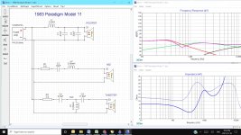
OK, so having stared at this a little longer, I think I've discovered the anomalies, the values notwithstanding. The components from the positive post to the tweeter lead to a black wire after the fuse, and the path back to the neg is a blue wire. Confusing at first, but I believe this is where the polarity of the tweeter is reversed. Then, the network on the tweeter itself makes sense. The values I measured are likely odd due to not being isolated, so I isolated the coils and checked again, but only the tweeter coil was different since there were 2 paths there. Although I would have liked to see the crossover points, this is as good as it gets for now, until I can find more info on the drivers themselves.
Attachments
Last edited:
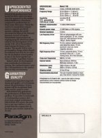
I have a working pair of 11se-mk1 from that time frame (original owner, no mods).
I've attached the spec for it. It's suppose to have a Vifa D19TD tweeter and variant of the Vifa D75M dome midrange but I've never opened them to verify that. The XO points should be 600Hz and 3.2Khz which you could verify if you included driver models in Xsim.
.
I've attached the spec for it. It's suppose to have a Vifa D19TD tweeter and variant of the Vifa D75M dome midrange but I've never opened them to verify that. The XO points should be 600Hz and 3.2Khz which you could verify if you included driver models in Xsim.
.
Attachments
The tweeter in the original post, looks like an Audax AW010 (non mag shielded version)
like as shown here,
Classic Paradigm Model 11 Speakers Photo #2965331 - Canuck Audio Mart
like as shown here,
Classic Paradigm Model 11 Speakers Photo #2965331 - Canuck Audio Mart
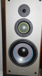
Actually, there appears to be a few variants of these depending on the production date. I've found numerous pics of others identical to mine in fact. I would prefer the soft dome to the mylar unit I have, but c'est la vie.....
Last edited:
- Home
- Loudspeakers
- Multi-Way
- Crossover confusion