I’ve been experimenting with the TPA3126D2 in filterless mode and am blown away by the results. Because it runs so cool I use them directly connected to the speakers in the enclosure so no need for speaker cables. While I know some folks worry about RF emissions, I’ve designed the speaker enclosures as grounded faraday cages to contain any possibility of becoming an unintentional radio station!
I’m wondering if others have experimented with some of the newer class-d amps in filterless mode. If anyone is interested I’m glad to share details and a PCB I’ve designed to minimize the layout size as well as provide extra power filtering and isolation of analog/switching power.
I’m wondering if others have experimented with some of the newer class-d amps in filterless mode. If anyone is interested I’m glad to share details and a PCB I’ve designed to minimize the layout size as well as provide extra power filtering and isolation of analog/switching power.
A few observations...
- I think HF/EMI will radiate out of the vice coil more or less in the same direction as the sound. Maybe if you also have a earthed metallic grill or conductive cloth as fronts.
- I think also this is interesting but cant help to observe that instead of depositing the heat of the filtered RF into a coil in a amp box, we are now sending it to the voicecoil - maybe not so good.
- The vibration caused by the sound pressure in the box might have a negative impact on the amp behaviour due to vibration.
- Instead of one cable, one now get two cables into the speaker - line level signal and power.
But I still think this is worth to pursue and could lead to an + net effect.
//
Maybe you want to try a test.
Put a generator on the input and then start with the highest frequency 40k or 20k depending on the sample rate of your sound card
move the frequency slowly down. When you hear a deeper tone rising in frequency you got aliasing and better put the filter.
Best is to use a headphone for this to dampen the environment noise.
What Type of filter were you using before? Those tiny square ferrite things, or larger toroidal ferrite things. An active speaker should work well with class D, you can tailor the filter to the specific impedance of the driver ( I'd be tempted to at least have one between the amp and tweeter, if it's a multi way ) The inductance of the voice coil should help filter some radio frequencies .
I’m using the filterless class-d as part of a not-quite full range desktop speaker system with an electronic 4th order crossover. The wide-range speaker (small, 2” for nearly point-source near field listening) crosses over at about 180Hz and is augmented by a single woofer (also with a mono filterless class-d amp).
I haven’t detected any microphonics from the electronics inside the speakers (no ceramic caps). I’m also using a DIY version of the Warpspeed attenuator - which really took the system to a new level).
I haven’t detected any microphonics from the electronics inside the speakers (no ceramic caps). I’m also using a DIY version of the Warpspeed attenuator - which really took the system to a new level).
What Type of filter were you using before? Those tiny square ferrite things, or larger toroidal ferrite things. An active speaker should work well with class D, you can tailor the filter to the specific impedance of the driver ( I'd be tempted to at least have one between the amp and tweeter, if it's a multi way ) The inductance of the voice coil should help filter some radio frequencies .
I’ve used all types of filters in earlier versions, but the filterless version always sounds much better. I’ve also done some monitoring of the coil temperature (with a sacrificed driver and temperature probe) and it never gets more than a few degrees above room temperature, which surprised me.
A few observations...
- I think HF/EMI will radiate out of the vice coil more or less in the same direction as the sound. Maybe if you also have a earthed metallic grill or conductive cloth as fronts.
- I think also this is interesting but cant help to observe that instead of depositing the heat of the filtered RF into a coil in a amp box, we are now sending it to the voicecoil - maybe not so good.
- The vibration caused by the sound pressure in the box might have a negative impact on the amp behaviour due to vibration.
- Instead of one cable, one now get two cables into the speaker - line level signal and power.
But I still think this is worth to pursue and could lead to an + net effect.
//
I’ve addressed some of your points in other messages, but regarding RF/EMI, I have done some tests with an RFExplorer and haven’t picked up any emissions from any orientation. I’ve also grounded the entire magnet and speaker basket/cage. I really don’t think RF is an issue.
Your point about power/signal wires, I actually have two separate power sources, one for the analog part of the chip and the other for the switching power. I have found that doing this, and adding a variety of low capacitance surface mount isolation caps VERY close to the chip, dramatically improves the sound compared to a single power source without extensive filtering.
@Peterm100,
Without an input signal (idle mode), have you measured the idle mode current consumption with an 4 or 8 Ohm driver as load? At which supply voltage?
Without an input signal (idle mode), have you measured the idle mode current consumption with an 4 or 8 Ohm driver as load? At which supply voltage?
@Peterm100,
Without an input signal (idle mode), have you measured the idle mode current consumption with an 4 or 8 Ohm driver as load? At which supply voltage?
No, I haven’t done that but it would be interesting. The TPA3126D2 data sheet boasts very low idle current so based on that I’d expect it to be very low, but haven’t confirmed it in my system.
PHP:
[WIKI][ATTACH]911452._xfImport[/ATTACH][/WIKI]No, I haven’t done that but it would be interesting. The TPA3126D2 data sheet boasts very low idle current so based on that I’d expect it to be very low, but haven’t confirmed it in my system.
Here’s the idle current plot from the Data sheet...

My feeling is that you will measure a much higher idle current consumption than stated in the datasheet. A central question is what is the equivalent impedance of a speaker driver at 400KHz?
Here in Europe it is close to midnight so I will explain tomorrow.
Here in Europe it is close to midnight so I will explain tomorrow.
My feeling is that you will measure a much higher idle current consumption than stated in the datasheet. A central question is what is the equivalent impedance of a speaker driver at 400KHz?
Here in Europe it is close to midnight so I will explain tomorrow.
It’s my understanding that the resistance at those frequencies is dependent on the specific driver, but I will say that the amps continue to drive the speakers when I shut the system down for about 30 seconds, just from the caps in the power supply, so to me that indicates a fairly low current drain, but I’d have to review how much capacitance is upstream.
Are these made in Kicad? If so I´d be interested to take a look.I’m wondering if others have experimented with some of the newer class-d amps in filterless mode. If anyone is interested I’m glad to share details and a PCB I’ve designed to minimize the layout size as well as provide extra power filtering and isolation of analog/switching power.
Do you have PCBs left and did you get the chip populated externally?
Best regards
Jens
I have always a priori seen class D without an output filter as something for low power use and very cheap designs. Actually, the PAM-chips can run without an output filter and sound surprisingly well. But for TPA3116 and the higher power level, I assumed the EMI to be unacceptably high. Puzzled by your results I started thinking about how an equivalent circuit would look without an output filter.
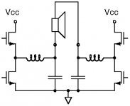
First the function with an output filter (circuit 1 as appended). It is possible to modulate the output voltage due to the output filter by varying the duty-cycle of the carrier square-wave signal (typically 400KHz). Because the impedance of the output filter choke is much higher than the load impedance at the carrier frequency, but much lower at audio frequencies, such regulation is possible similar to the functioning of a Buck converter.
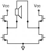
When the output filter is removed, the carrier signal looks directly into the load (speaker; circuit 2 as appended). First order I would expect the speaker to resemble a resistor (the speaker driver DC impedance) in series with an inductance (from the speaker driver coil). I would expect the inductance to be low because eddy-currents inducted from the coil to the speaker driver pole-piece (probably MU-metal) should reduce the inductance value. I would expect the DC impedance to be dominating of the two. If the class D amplifier is used without an output filter and operating with traditional PWM, the load (speaker) always sees the supply voltage of the class D amplifier and the coil should try to move back-and-forth at the carrier frequency but can’t due to the diaphragm mass and air mass. As result, it should result in high power loss. This was why I asked you to check the idle current consumption. But you are right, the time it takes to bleed-off the charge on the power rail decoupling capacitors is an indication of current consumption. You indicate that this takes time.
There is a different possibility with much less power loss and still no output filter – the possibility that the TPA3116D2 uses its BTL configuration to change traditional PWM modulation into PDM (Pulse Duration Modulation). This is possible by phase-advancing or phase-delaying some switching edges on the carrier signals with respect to one another (drawing 3 as appended). This way the load (speaker driver) will still see the full amplifier supply voltage but only in short moments while in periods the speaker terminals are effectively short-circuited (no voltage). The current surges from the supply rail will be important and that could fit with your observation that good decoupling is important for the sound.
If the TPA3116D2 actually uses such PDM modulation, the operational principle is rather reliable. It can be checked if that is the case with a two-channel oscilloscope but at present I am disabled. I believe you can bring the EMI down to a reasonable level by having very short wires and use some screening as you suggest.
Good luck with the project.
First the function with an output filter (circuit 1 as appended). It is possible to modulate the output voltage due to the output filter by varying the duty-cycle of the carrier square-wave signal (typically 400KHz). Because the impedance of the output filter choke is much higher than the load impedance at the carrier frequency, but much lower at audio frequencies, such regulation is possible similar to the functioning of a Buck converter.
When the output filter is removed, the carrier signal looks directly into the load (speaker; circuit 2 as appended). First order I would expect the speaker to resemble a resistor (the speaker driver DC impedance) in series with an inductance (from the speaker driver coil). I would expect the inductance to be low because eddy-currents inducted from the coil to the speaker driver pole-piece (probably MU-metal) should reduce the inductance value. I would expect the DC impedance to be dominating of the two. If the class D amplifier is used without an output filter and operating with traditional PWM, the load (speaker) always sees the supply voltage of the class D amplifier and the coil should try to move back-and-forth at the carrier frequency but can’t due to the diaphragm mass and air mass. As result, it should result in high power loss. This was why I asked you to check the idle current consumption. But you are right, the time it takes to bleed-off the charge on the power rail decoupling capacitors is an indication of current consumption. You indicate that this takes time.
There is a different possibility with much less power loss and still no output filter – the possibility that the TPA3116D2 uses its BTL configuration to change traditional PWM modulation into PDM (Pulse Duration Modulation). This is possible by phase-advancing or phase-delaying some switching edges on the carrier signals with respect to one another (drawing 3 as appended). This way the load (speaker driver) will still see the full amplifier supply voltage but only in short moments while in periods the speaker terminals are effectively short-circuited (no voltage). The current surges from the supply rail will be important and that could fit with your observation that good decoupling is important for the sound.
If the TPA3116D2 actually uses such PDM modulation, the operational principle is rather reliable. It can be checked if that is the case with a two-channel oscilloscope but at present I am disabled. I believe you can bring the EMI down to a reasonable level by having very short wires and use some screening as you suggest.
Good luck with the project.
Attachments

Are these made in Kicad? If so I´d be interested to take a look.
Do you have PCBs left and did you get the chip populated externally?
Best regards
Jens
Yes, the pcbs were created in kicad and I’m happy to share the files, or alternately I’m about to produce another batch of pcbs and I can make some extras. I populated them myself. I’m currently making a small tweak to the design to more cleanly separate the two power inputs. Sorry to be so brief, work is calling!
Are these made in Kicad? If so I´d be interested to take a look.
Do you have PCBs left and did you get the chip populated externally?
Best regards
Jens
I have always a priori seen class D without an output filter as something for low power use and very cheap designs. Actually, the PAM-chips can run without an output filter and sound surprisingly well. But for TPA3116 and the higher power level, I assumed the EMI to be unacceptably high. Puzzled by your results I started thinking about how an equivalent circuit would look without an output filter.
First the function with an output filter (circuit 1 as appended). It is possible to modulate the output voltage due to the output filter by varying the duty-cycle of the carrier square-wave signal (typically 400KHz). Because the impedance of the output filter choke is much higher than the load impedance at the carrier frequency, but much lower at audio frequencies, such regulation is possible similar to the functioning of a Buck converter.
When the output filter is removed, the carrier signal looks directly into the load (speaker; circuit 2 as appended). First order I would expect the speaker to resemble a resistor (the speaker driver DC impedance) in series with an inductance (from the speaker driver coil). I would expect the inductance to be low because eddy-currents inducted from the coil to the speaker driver pole-piece (probably MU-metal) should reduce the inductance value. I would expect the DC impedance to be dominating of the two. If the class D amplifier is used without an output filter and operating with traditional PWM, the load (speaker) always sees the supply voltage of the class D amplifier and the coil should try to move back-and-forth at the carrier frequency but can’t due to the diaphragm mass and air mass. As result, it should result in high power loss. This was why I asked you to check the idle current consumption. But you are right, the time it takes to bleed-off the charge on the power rail decoupling capacitors is an indication of current consumption. You indicate that this takes time.
There is a different possibility with much less power loss and still no output filter – the possibility that the TPA3116D2 uses its BTL configuration to change traditional PWM modulation into PDM (Pulse Duration Modulation). This is possible by phase-advancing or phase-delaying some switching edges on the carrier signals with respect to one another (drawing 3 as appended). This way the load (speaker driver) will still see the full amplifier supply voltage but only in short moments while in periods the speaker terminals are effectively short-circuited (no voltage). The current surges from the supply rail will be important and that could fit with your observation that good decoupling is important for the sound.
If the TPA3116D2 actually uses such PDM modulation, the operational principle is rather reliable. It can be checked if that is the case with a two-channel oscilloscope but at present I am disabled. I believe you can bring the EMI down to a reasonable level by having very short wires and use some screening as you suggest.
Good luck with the project.
Apologies in advance for the briefness, I’ll take more time later to dive deeper into your message - thanks for the perspectives! Work is conflicting with hobbies!
First, to be clear, my experiments are using the newer TPA3126D2 chip (not the 3116, although the pin assignments are essentially the same) in hybrid mono PBTL mode. I have done lots of experimentation with the 3116, but now I’m convinced that the 3126 in “ultra low idle current” mode is superior. They run very cool in my system (only get slightly warm to the touch) and as I said, the sound quality is exceptional compared to any other class d amps I’ve used.
I look forward to continuing this discussion when I get a chunk of time!
I think this text from the 3126 data sheet on the BD Modulation mode provides a good explanation of the method used to produce low idle currents:
This is a modulation scheme that allows operation without the classic LC reconstruction filter when the amp is driving an inductive load with short speaker wires. Each output is switching from 0 volts to the supply voltage. The OUTPx and OUTNx are in phase with each other with no input so that there is little or no current in the speaker. The duty cycle of OUTPx is greater than 50% and OUTNx is less than 50% for positive output voltages. The duty cycle of OUTPx is less than 50% and OUTNx is greater than 50% for negative output voltages. The voltage across the load sits at 0V throughout most of the switching period, reducing the switching current, which reduces any I2R losses in the load.
Again this is not a feature of the 3116 chip.
I cannot emphasize how great this amp sounds for my desktop system. My next experiment is to drive my larger wide-range system with these amps. Currently this system is being driven by a refurbished ST70 tube amp (with a modern power supply) which is my reference system, however, my desktop system with the individual mono 3126 amps sounds remarkably good even in comparison to my reference system - don’t discount class-d when optimized with lots of decoupling and sans speaker cables and filter.
When I write "TPA3116" I mean "TPA3116D2". I have not known the previous TPA3116.
Thanks for the reference to 3126 modulation. One day I will set up one of my many TPA3116D2 boards directly on the load and bypass the output filter. With my oscilloscope it should be possible to get an idea about what kind of modulation the TPA3116D2 uses and why it can operate straight into the load.
In your case, if it works and no excessive current is drawn, if the TPA3116D2 chip does become suspiciously warm and it sounds good, just go ahead. I may use your results one day.
I can already conclude that I have far less knowedgle about class D topology that most guys here, but I'd like to tag along for this ride if that's ok. I am working on a similar project, and have made my own pcb design for an active analog Linkwitz-Riley crossover and preamp. For the next phase I was planning a filter less Tpa3116d2 design, but now I am tempted to look into the tpa3126 chip. I would very much be interested in the pcb design files if you would be willing to share them
When I write "TPA3116" I mean "TPA3116D2". I have not known the previous TPA3116.
Thanks for the reference to 3126 modulation. One day I will set up one of my many TPA3116D2 boards directly on the load and bypass the output filter. With my oscilloscope it should be possible to get an idea about what kind of modulation the TPA3116D2 uses and why it can operate straight into the load.
In your case, if it works and no excessive current is drawn, if the TPA3116D2 chip does become suspiciously warm and it sounds good, just go ahead. I may use your results one day.
As I’m sure you realize, if you are going to use the 3116 in filterless mode make sure it is in BD mode, pin 1 to ground and keep speaker cables under 8” to avoid excessive RF. Of course all of this is in the data sheet as well as details on modulation modes.
- Home
- Amplifiers
- Class D
- Filterless Class D with TPA3126D2