Hello, me again...
I‘m in the pre-final stage 😇 of my F4 build, connscting stuff.
There will be 1 connection through a ICL to the chassis from the PSU (and the amp-boards connected to the PSU), the connection of the IEC safery earth, and there‘s a last one, the toroidy transformer...
I‘m not sure wether I should connect them all to 1 point only, or wether it is ok to have the star-ground on one end of the chassis, and iec-safety-earth & toroid at the other end?
Or even something else?
Thank you for advices!
Safety ground (from IEC) MUST have its own screw, NOT used for anything else. That is by safety legislation.
The remainder are to suit.
Usual advice is a single star ground but it is not always necessary or convenient.
Study this and take as much or as little as you need from it.
Audio Component Grounding and Interconnection - diyAudio
The remainder are to suit.
Usual advice is a single star ground but it is not always necessary or convenient.
Study this and take as much or as little as you need from it.
Audio Component Grounding and Interconnection - diyAudio
Thanks RusscSafety ground (from IEC) MUST have its own screw, NOT used for anything else. That is by safety legislation.
Will have to work a bit on that document, not too ease read for me.
That one safety IEC screw—that is really the screw, and not just the bolt?
I was going to screw down the safety ground and then the PSU GND onto that same, as I read someplace I thought was trustworthy. Plus, if I see it correctly, 6L6 did so in the build guide...
Anyway, no worries, I just try to follow the best practice / best method path...
...
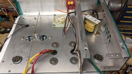
When attaching the ground wire to the chassis, be sure that any paint or other insulating finish is scraped away from the place where the wire will go. Makes no difference where on the chassis the ground is mounted.
....That one safety IEC screw—that is really the screw, and not just the bolt?
I was going to screw down the safety ground and then the PSU GND onto that same, as I read someplace I thought was trustworthy. ...
No, *only* the wall-ground to case connection. The idea is that, in later years, some technician may disconnect grounds to replace parts/boards. And then forget to RE-connect the vital case-safety ground. So no other ground can share that screw.
In DIY you "may" do as you please, as long as nothing goes wrong. But a dedicated screw costs pennies. And if you think you need another "trustworthy" screw, get another screw.
Thanks, guys!
yup, will do it all:
1 screw IEC safety ground, nothing else
1 screw with toroid's primary-ground, and PSU ground behind CL60. (still not sure about the toroid, but I'll see...)
follow-up question: Does it make sense to sand off the anodized stuff where the chassis-parts are connected, to make sure the whole box "has continuity"?
thanks you
A "T" is better than a star ground. http://hifisonix.com/wordpress/wp-content/uploads/2019/02/Ground-Loops.pdf Page 42 etc
and there‘s a last one, the toroidy transformer...
Are you referring to the shield of the Toroidy? This wire should be as short as possible. I usually don't take this to the "main" earth point.
Are you referring to the shield of the Toroidy? This wire should be as short as possible. I usually don't take this to the "main" earth point.
Yes, this is the shield (must be).
As short as possible ( a 2.nd meaning of „ASAP“[emoji1782]) sounds very good.
No ground-lifting like CL60 is correct?
where your grounds attach.
yes, where the ground attach I will clearly, surely remove anodization.
Question was wether I should remove it where the chassis-parts connect (front, back, heatsinks, top & bottom), say 1 connection/screw @ each?
(Anodization has a "dielectric strength" of ~900V @ 30 µm...)
Which in fact answers my question, of sorts... Anodization removal will be about an hour time.
Yes, this is the shield (must be).
As short as possible ( a 2.nd meaning of „ASAP“[emoji1782]) sounds very good.
No ground-lifting like CL60 is correct?
No CL60 or other ground loop breaker. See here: AnTek Toroid Grounding
No CL60 or other ground loop breaker. See here: AnTek Toroid Grounding
Aah, thank you mr. Mbrennwa [emoji4] that’s what I was thinking without further knowledge.
andrewt‘s reply was again very precise.
On the chassis I powder coat I make sure there is a large area of uncoated are between the panels.
But I'm not an expert by any means!
But I'm not an expert by any means!
Attachments
- Home
- Design & Build
- Construction Tips
- Chassis ground on several places