Another option would be installing sockets in the R4 location, use a temporary trimpot installed into the sockets to find the value needed for 10mA, replace with a fixed resistor and solder it in.
A hands on diy mod for personal satisfaction and an accurate way to arrive at the proper resistor value, the best of both worlds 🙂
A hands on diy mod for personal satisfaction and an accurate way to arrive at the proper resistor value, the best of both worlds 🙂
Last edited:
I recently ‘finalized’ my build by pulling the pin sockets that I used to play with different values and soldering in the final value (62R, straight from Mark’s list 🙂 Works great.
Another option would be installing sockets in the R4 location, use a temporary trimpot installed into the sockets to find the value needed for 10mA, replace with a fixed resistor and solder it in.
A hands on diy mod for personal satisfaction and an accurate way to arrive at the proper resistor value, the best of both worlds 🙂
This is exactly what I did. Got the fixed resistors a few days ago, now just need to solder them in now that I Christmas is past and I have a week off before I have to go back to work 😉
I think so too. When a builder hand-picks resistors her/himself, it makes the project more personal, more *I* did that, more intimately connected. Nelson Pass and his squad trusted *me* to choose the right resistor, and I did, and the result sounds great. *My* ACP+ that *I* built, sounds great.
That is a fair point; its exactly how I've learned a lot about the circuit myself. 🙂
--Tom
Question regarding building this with a linear power supply. I posted earlier about using a CapMX multiplier board with transformer that I usually use on my Amp camp builds. I bought a 24V secondary transformer and tested it on my CapMX power supply today and the rail voltage was 35V. I understand it will sag once I add in the ACP, but any harm in the ACP having higher voltages as I don’t see the voltage sagging enough to get down to 24V?
Below is a pic of the CapMX with the voltage reading.
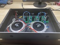
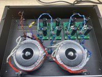
Here is an update on my progress to build an external power supply for my ACP and also amp camp ACA. My plan is to use the external power supply to power one ACP and one ACA or two ACA. The torroidals are 22V secondaries which gives me 31V, but once I load the CapMX power supplies, I see the voltage drop approx 4-5 V volts down to 27V and I am able to lower the voltage on the power board even more with the included 50k pot.
I confirmed the voltage decrease by adding a voltage regulator and checking the voltage drop before the regulator which is 27 volts. My question is, can I get away with running the ACP on 27 volts without harm to avoid using the added regulator?
See pics below of my build.
Attachments
Last edited by a moderator:
You should be fine.
If you are still worried you can increase R8 to 220 - 330 ohm and that will bring you back to approx. 24V.
Of course you can also play with R18, 19, 20, 21 and introduce some voltage drop but it becomes more complicated, re. voltage and power dissipation.
So many ways to skin a PSU.
If you are still worried you can increase R8 to 220 - 330 ohm and that will bring you back to approx. 24V.
Of course you can also play with R18, 19, 20, 21 and introduce some voltage drop but it becomes more complicated, re. voltage and power dissipation.
So many ways to skin a PSU.
Last edited by a moderator:
Here is an update on my progress to build an external power supply for my ACP and also amp camp ACA. My plan is to use the external power supply to power one ACP and one ACA or two ACA. The torroidals are 22V secondaries which gives me 31V, but once I load the CapMX power supplies, I see the voltage drop approx 4-5 V volts down to 27V and I am able to lower the voltage on the power board even more with the included 50k pot.
I confirmed the voltage decrease by adding a voltage regulator and checking the voltage drop before the regulator which is 27 volts. My question is, can I get away with running the ACP on 27 volts without harm to avoid using the added regulator?
See pics below of my build.
If you do go higher, note the input filter cap voltage ratings and the derating spec for the caps you are using. Caps are derated to some % over their rated voltage and all vary, so check the sheet. More is generally a better idea and they will last longer if using lower voltages - usually. The BOM we published earlier in this thread (and what we are using to build the diyaudio kits now) has caps that are 35v and 50v so you will be ok if you use those for sure, but if you choose your own or use Nelson's BOM which specifies 25v caps you might want to make sure they will work with that input voltage.
--Tom
Troubleshooting help request
ACP+ ran fine for a few weeks. Then one day I went to adjust the volume, got an audible “tick” when I touched the pot, I assume the “tick” was a static discharge. Now there is audible noise, mostly on the right channel but a little on the left channel. The noise level increases and decrease with pot position . I thought the pot was defective, replaced with a new one, still has the noise. Went through the startup checks in the build guide. The L channel measures 11.6v at DC1, the R channel 5.24v, not good. Measured the temps of the screws holding Q5 and Q6 with a meat thermometer. L channel Q5 and Q6 are 93 and 101 deg F. R channel Q5 and Q6 are 120 and 84 deg F, seems like and feels like a big difference. Ambient was 59 deg F. I’ve inspected the board for bad soldering or burned components, beefed up the soldering on the headphone jack and input selector but haven’t found anything else. And now I’m stuck, any help would be appreciated.
ACP+ ran fine for a few weeks. Then one day I went to adjust the volume, got an audible “tick” when I touched the pot, I assume the “tick” was a static discharge. Now there is audible noise, mostly on the right channel but a little on the left channel. The noise level increases and decrease with pot position . I thought the pot was defective, replaced with a new one, still has the noise. Went through the startup checks in the build guide. The L channel measures 11.6v at DC1, the R channel 5.24v, not good. Measured the temps of the screws holding Q5 and Q6 with a meat thermometer. L channel Q5 and Q6 are 93 and 101 deg F. R channel Q5 and Q6 are 120 and 84 deg F, seems like and feels like a big difference. Ambient was 59 deg F. I’ve inspected the board for bad soldering or burned components, beefed up the soldering on the headphone jack and input selector but haven’t found anything else. And now I’m stuck, any help would be appreciated.
Hi folks,
I have now finished building my ACP+. After turning it on, one resistor (R13) started to smoke. I turned it off and measured it - still working. After resoldering all points it now does work quite well - except the I get a humming noise as soon as I turn the ACP+ on and connect headphones. It is getting louder when I touch the poti. Can anyone suggest where the problem might be? Will swap the burned resistor as soon as possible. Can this do the trick? Thanks in advance!
I have now finished building my ACP+. After turning it on, one resistor (R13) started to smoke. I turned it off and measured it - still working. After resoldering all points it now does work quite well - except the I get a humming noise as soon as I turn the ACP+ on and connect headphones. It is getting louder when I touch the poti. Can anyone suggest where the problem might be? Will swap the burned resistor as soon as possible. Can this do the trick? Thanks in advance!
put proper size resistor in R13 position - 0207 size, same as you use for R12, for example
there is substantial dissipation for that small one
hum-buzz - confirm PSU voltage
screw thin wire with pot nut and solder wire to closest GND pad, that way you'll get pot case silent
do you have additional under-plate pcb, for shielding?
also, compare voltages across R12 in both channels, write here
Has anyone had issues with the Triad wall warts and the ACP+? I used the one that came with my B1Korg. On that device it is perfectly silent at full volume. The Triad is plugged in via a shaver adaptor as it is a US spec 2-pin device.
I've spent several hours chasing what appears to have been an earthing issue. Up to about half volume no problem, but then a mains hum that increased with turning the volume further or if I touched any ground point such as the RCA shield. Since I'd already established the Triad was silent with the B1Korg, I didn't look there initially. After checking the board several times and even removing the volume potentiometer just in case the fault was there, I still had the hum.
As a last resort, I plugged in the Meanwell SMPS that came with my ACA. Problem gone, total silence. Could the issue be related to it being US spec on a UK earthing system perhaps? I'd be interested in hearing people's thoughts.
This is a very nice sounding device, even with the cheap potentiometer I'm testing it with. I'm looking forward to wiring it up with a relay based volume control later this week before giving it a serious listen though.
Thanks to NP and the diyaudiostore for yet another excellent product.
well, simple as that - it's either working good, or it is working bad
having audio GND connected to safety GND (in one of variety of possible arrangements) certainly helps , and with KB1 there you most likely had some other piece of equipment (source,amp) connected to safety GND
what is a source, in case of ACP+ misbehaving, with Triad?
having audio GND connected to safety GND (in one of variety of possible arrangements) certainly helps , and with KB1 there you most likely had some other piece of equipment (source,amp) connected to safety GND
what is a source, in case of ACP+ misbehaving, with Triad?
The hum was independent of source being connected or not connected to the ACP+.
The B1K is usually connected to an ACA so the Meanwell would be present there too.
The B1K is usually connected to an ACA so the Meanwell would be present there too.
Troubleshooting help request
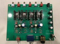
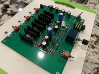
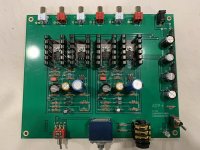
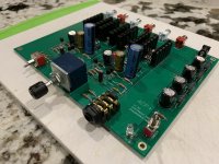
First time posting pics, let me know if this is correct, used “large” format. These are the follow up to my previous post about having noise after several weeks of good operation. 24v at the board, DC1 measure differently between R and L channels.
First time posting pics, let me know if this is correct, used “large” format. These are the follow up to my previous post about having noise after several weeks of good operation. 24v at the board, DC1 measure differently between R and L channels.
Attachments

clumsy bent mosfet pins
check that you don't have contact with heatsinks
no need for silpads between sinks and mosfets
reflow any suspect soldering joint
what's voltage across R13 , both channels
what's voltage across R4, both
what's voltage across R15, both
check that you don't have contact with heatsinks
no need for silpads between sinks and mosfets
reflow any suspect soldering joint
what's voltage across R13 , both channels
what's voltage across R4, both
what's voltage across R15, both
- Home
- Amplifiers
- Pass Labs
- Amp Camp Pre+Headphone Amp - ACP+