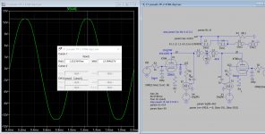
Simulation says if you adjust for 20Vrms unloaded, you get 8.2V rms loaded with 8.5 ohms, close enough to what you are seeing. Also says that gain is very low, you need more than 6V rms to drive to full power (50W into 8.5 ohms assuming 5k primary as per the Sowter data). This needed ~40V rms drive to KT88s, bias was -59V to give 50 mA.
Are you driving both inputs differentially?
Driving only one input, and grounding the other will not work properly.
Driving only one input, and grounding the other will not work properly.
Why not? That's what the original designer has done. Gain is halved but the CCS in the tail forces balance, so long as it has sufficient headroom.
With a clean 36V rms on the grid, the output with 8.5 ohm load is a badly distorted 19.2 V rms. According to the GEC data it should be about 2% distortion, it looks a lot worse than that to me. I don't have a distortion meter. I can't understand how the Bill design without feedback can be considered good if this is the result.....
How badly distorted is it, Thd=?%
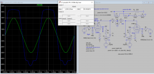
This is what you expect to see between no-load and 8 ohms load with input level=bias level. Thd 4.65% @55W Pout.
Attachments
Last edited:
tikiroo,
Just as you said, the gain when driving only one side is 1/2 the gain of driving both sides differentially.
It is possible that with lower gain, and depending on where clipping occurs in the input stage, when you drive only one input, that you will only get 1/2 the voltage at the output too. That is -6dB, or 1/4 Power.
That might explain the low power out.
Now, you know why I asked the question.
Thanks for all the observations folks. Koonw. I don't have a distortion meter, but the waveform I get is not as badly distorted as your simulation shows. I'm surprised that is only 4.65%, looks worse to me! It seems my expectations of performance without feedback is way too high and that I need more drive than the 36Vrms I was using. I can't understand why the Bill open loop design is considered good with such a distorted output. I'll add another stage and some feedback and see what happens. Thanks again folks, for all your assistance. M
The blue line is no load and is severely clipping, the green line is with 8 ohms at the same drive level. The green is 4.65%. At 50W I get <3% distortion in simulation. Not too bad for no global feedback. The output impedance is ~12 ohms so will not have a flat frequency response with typical loudspeaker impedance peaks. The Triode Bill design is simple and might appeal to some, but there are plenty of better designs out there.
Last edited:
tikiroo,
Just as you said, the gain when driving only one side is 1/2 the gain of driving both sides differentially.
It is possible that with lower gain, and depending on where clipping occurs in the input stage, when you drive only one input, that you will only get 1/2 the voltage at the output too. That is -6dB, or 1/4 Power.
That might explain the low power out.
Now, you know why I asked the question.
No worries. The input stage operating point is fine, it's well away from clipping even when driven single ended by the required 6.5Vrms for full power - simulation shows 9.5V on the cathodes for 15 mA tail current.
Would be interesting to know what the actual maximum voltage into 8 ohms was at the onset of clipping - as Koonw says, should be just over 20V rms, but a couple of volts less wouldn't be surprising.
tikiroo. I can get 20Vrms before clipping, but the waveform is starting to kink and triangulate. This gets much worse as the frequency is increased. If I drop the frequency to around 80Hz, it looks quite good. However if it's taken to 30Hz the transformer windings rattle badly.
Matt Rowland,
1. Make sure that the 'Push' plate current and screen current,
versus the 'Pull' plate current and screen currents respectively are exactly equal.
One of the first characteristics of un-balanced currents in the output transformer is poor performance at Bass frequencies.
(early lamination saturation).
2. At what high frequency is the waveform starting to kink and triangulate?
That sound like slew limiting.
3. Because this is an Ultra Linear output stage, there is some Miller Effect Capacitance loading of the driver stage.
For Triode Mode connection, the Miller Effect Capacitance is even larger.
4. What model output transformer are you using?
A KT88 at 40% Ultra Linear tap, might have a plate resistance, rp, of perhaps 2k to 3k Ohms.
Calculate the damping factor using the output tubes rp and transformer primary impedance you have.
5. What is the primary DCR?
What is the secondary DCR?
If both those values are 5% of the rated impedance, then the insertion loss is 1 dB.
20 Watts of signal power from the plates to the primary, becomes only 15.9 Watts out of the secondary.
Last edited:
Maybe that output transformer is not configured as it should , it seems the most likely cause , the Raa is not optimal so the output is low .
A square wave test at reduced output would be useful. Seems that transformer isn't behaving quite right, have you tested the other one?
6A3sUMMER - the transformer specs are in the first post, it is a Sowter with four secondary sections which should be very good. Primary DCR 150 ohms AA.
6A3sUMMER - the transformer specs are in the first post, it is a Sowter with four secondary sections which should be very good. Primary DCR 150 ohms AA.
The Sowter transformer specs seem fine.
But the data sheet mentions a specific MO Valve application note for KT88s.
I am pretty sure the MO Valve Report 3 application note uses Negative Feedback.
I notice the anode to anode impedance is 5k.
5k a-a, is 1.25k from a to center tap.
That may be a little too low for KT88s in push pull with Ultra Linear rp of about 2k to 3k, when there is no negative feedback.
Damping factor will be low, and so when the output is loaded, the output voltage will be reduced a lot.
In the class A region, it is effectively two parallel 2k rp's (1k total) driving 2.5k.
Damping factor 2.5
Or, In the class A region, it is effectively two parallel 3k rp's (1.5k total) driving 2.5k.
Damping factor 1.67.
When one tube goes into cutoff (Class AB), it is 2k rp driving 1.25k, or 3k rp driving 1.25k.
Those are damping factors of 0.625 and 0.417.
In Class AB, the waveforms will be severely clipped when working into a load.
Perhaps I did a poor estimate of rp, but even if the Ultra Linear rp is between 1k and 1.5k, you can see the effect of not using any negative feedback, but using only 5k a-a impedance.
Just my opinions.
Last edited:
6A3sUMMER. Thanks for the reply. I've had to put the project aside right now. But to answer some of your questions.
The anode currents were balanced. I didn't check the screen currents.
The wave form started to deteriorate badly after a few kHz (although the driver stage stayed fine). I could get the driver up to 36 volts rms each side before clipping, which gave 20 volts rms into 8.5 ohms on the o/p @1kHz.
I measured the primary windings resistances and they were anode to screen- 36.8R, anode to centre, 70.3R, both halves exactly the same. The secondaries measured 37.4r, 33.8R, 34.3R,37.3R.
I applied 19.7 volts 50Hz to the 8R configured secondary and got 425 volts anode to anode on the primary. I calculate that as about 3.9K ohms , a little lower than the manufacturer's 5k spec. See my earlier post with Sowter spec sheets attached for the x'fmr.
Depanatoru. I have tried playing with the secondary winding configuration without solving the issue.
Clearly I need a stronger driver and some feedback. However, I still think there is something else amiss, as the performance would not be so poor across the frequency band even with this driver design. I'll get back to it when time permits. Thanks for all the help. M
Last edited:
6A3sUMMER. Our posts just crossed! Interesting observations and appreciated. I'll look closely at what you've pointed out, as it seems a likely explanation. Best. Matt
From KT88 datasheet Raa should be around 4K in this situation so this is aprox correct .
The output transformer can be put at mains voltage 230V~ to see if heats up or something is wrong with it exactly like a power transformer . This is also the correct way to calculate Raa , not from secondary .
The output transformer can be put at mains voltage 230V~ to see if heats up or something is wrong with it exactly like a power transformer . This is also the correct way to calculate Raa , not from secondary .
Last edited:
Hint:
Use '8 Ohm' speakers (typically 6 Ohm minimum impedance at some frequencies),
and connect the secondaries for the 4 Ohm setup.
The power will be a little low, but I bet it sounds very good in the Class A region, on a number of good loudspeaker models.
Listen, and have fun!
Use '8 Ohm' speakers (typically 6 Ohm minimum impedance at some frequencies),
and connect the secondaries for the 4 Ohm setup.
The power will be a little low, but I bet it sounds very good in the Class A region, on a number of good loudspeaker models.
Listen, and have fun!
Depanatoru,
The second page of the Sowter spec (on Post # 1), says Sowter designed the transformer to be 5k a-a, not 4k.
The KT88 data sheet is a separate issue.
Operating KT88 tubes in push pull with medium to low a-a impedance, and negative feedback gives lots of output power.
However, operating KT88 tubes in push pull with medium to low a-a impedance, without negative feedback, does not give lots of output power.
In that case, a pair of 300B tubes in push pull with medium to low a-a impedance, without negative feedback, will give more output power than a pair of KT88 tubes that do not use negative feedback.
Just Sayin'
Last edited:
6A3sUMMER. Yes, you are correct. I think I got the 4K from the GEC spec for operating AB1, fixed bias, ultralinear at 460V, 50mA. My calculations from the voltage ratio I measured was around 4K, so Sowter's spec seems a bit out.
- Home
- Amplifiers
- Tubes / Valves
- New year trouble shooting a KT88 output stage