When I power the amp up and feed it 100Hz sinewave with no output fets the signal on the pads is a 100Hz 5v ac switching wave. Shouldnt it be much larger? The rail voltage is +/- 179vdc.
Last edited:
The amplitude of the voltage for the drive an an FET is typically 10v, measured source to gate. A 10v square wave may read as 5v AC.
Do all of the 4(?) driver ICs produce the same heating?
Install a temporary heatsink on them if they heat up too quickly to get a photo of the drive waveform.
Post photos of the drive waveforms with your handheld scope. Black on the source, red on the gate. Do this for one high and one low FET.
Install a temporary heatsink on them if they heat up too quickly to get a photo of the drive waveform.
Post photos of the drive waveforms with your handheld scope. Black on the source, red on the gate. Do this for one high and one low FET.
Does this happen for every driver IC?
Is the driver board being driven into shutdown?
Do you lose drive on the input of the ICs?
Is the driver board being driven into shutdown?
Do you lose drive on the input of the ICs?
Ok heres where im at now. there is .5vdc on all the mosfet pads that should have 0vdc. When i take the driver card out the .5vdc goes away but the card works in other amps. also the .5vdc is present with the card in even with no drive ic's installed. Any ideas?
Is the DC offset protection engaging?
What is the DC voltage (referenced to the negative rail) on pin 2 of the driver ICs?
What is the DC voltage (referenced to the negative rail) on pin 2 of the driver ICs?
should i be using the main ground or speaker terminal when i check rail votages? if i use the neg speaker terminal the voltages are all correct.
You're not measuring the rail voltage. You're measuring voltage on the IC.
All of the IC voltages (except the 3 high-side terminals) are referenced to the negative rail so that's where you have to place your black meter probe when measuring voltage on the IC.
The negative rectifier output or the wire-type shunt resistors are generally the easiest points to place the black probe.
not protecting but the fets heat upIs the DC offset protection engaging?
What is the DC voltage (referenced to the negative rail) on pin 2 of the driver ICs?
4.7vdc for both
Do you see the drive signal on pin 1 of the ICs?
If so, do you see the drive on the low-side output of the ICs?
If so, do you see the drive on the low-side output of the ICs?
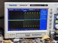
Why is your scope starting the waveform in the center of the sweep?
I don't understand what you wrote and the waveform don't make sense of the input or for the low-side drive.
Are you using your scope in differential mode?
I don't understand what you wrote and the waveform don't make sense of the input or for the low-side drive.
Are you using your scope in differential mode?
I had a similar problem.
It is not correct to say that the signal starts from the center of the sweep, instead I believe that the signal (when the amplifier is turned on) begins a cycle of start and end repeatedly (as if it started and stopped, as if it were undecided).
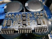
In the past I happened to rebuild the entire 4070 driverboard of an amplifier and see this defect, I looked everywhere, in the end the problem was the 4 4.7ohm 3watt resistors (VS resistors that can be of different value but still low other amplifiers with similar design) that connect the output point before the inductor of each stage (4 stages or 2 in the case of other smaller amplifiers) to the VS pin of each IRS21844.
Precisely, when I measured these resistors, they looked OK, maybe a little out of tolerance, but I assumed it was normal, instead it was not normal, the resistors had been damaged in the previous failure, in fact, by replacing them, the amplifier worked perfectly.
mnhiphop101, can I ask you to take a picture and show us the whole amplifier board and the type of driverboard used?
It is not correct to say that the signal starts from the center of the sweep, instead I believe that the signal (when the amplifier is turned on) begins a cycle of start and end repeatedly (as if it started and stopped, as if it were undecided).
In the past I happened to rebuild the entire 4070 driverboard of an amplifier and see this defect, I looked everywhere, in the end the problem was the 4 4.7ohm 3watt resistors (VS resistors that can be of different value but still low other amplifiers with similar design) that connect the output point before the inductor of each stage (4 stages or 2 in the case of other smaller amplifiers) to the VS pin of each IRS21844.
Precisely, when I measured these resistors, they looked OK, maybe a little out of tolerance, but I assumed it was normal, instead it was not normal, the resistors had been damaged in the previous failure, in fact, by replacing them, the amplifier worked perfectly.
mnhiphop101, can I ask you to take a picture and show us the whole amplifier board and the type of driverboard used?
I asked about the scope because someone else had the same problem with a hantek scope. It worked normally on the PS and another scope worked normally on the output stage but the hantek always had the oscillation start in the center of the sweep on the output stage.
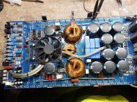
You were right MarioRestucci. This amp has a single 5w 100ohm resistor off of the small inductor in the middle. I Replaced it and the amp is functioning properly now. Ive been working on this amp for a while now and wouldn't have been able to get it fixed without the help of you and Perry. Thanks to both of you.
- Home
- General Interest
- Car Audio
- Ampere Audio 8k