Hi All,
Quick, question:
For the purposes of a plate load, is there any difference between a 4k and 8k wired in series, and a single 12k resistor?
Hope this is not a ridiculous question!
Thanks in advance for you help!
Best regards,
John
Quick, question:
For the purposes of a plate load, is there any difference between a 4k and 8k wired in series, and a single 12k resistor?
Hope this is not a ridiculous question!
Thanks in advance for you help!
Best regards,
John
Not really much difference, but sometimes series resistors are used to increase the net voltage rating.
Or the desired ohmic value may not be a standard value for that part.
Also, since the parasitic shunt capacitance tends to be about the same, independent of ohmic value,
you can make a wider bandwidth resistor with two series resistors, each of half the desired value.
This is since two similar capacitors in series give half their individual values.
Last edited:
Thanks for the blazing fast response, Rayma!
I need a ~12k plate load, but find that nearest equivalent my part box can provide me is a 4k+8k series combo.
Best!
John
I need a ~12k plate load, but find that nearest equivalent my part box can provide me is a 4k+8k series combo.
Best!
John
Note:
For high power rated resistors, many are wirewound.
If you use wirewound resistors, they will have inductance.
The total series impedance will go up as the signal frequency increases.
There are non-inductive wirewound, but most are not.
The non-inductive wirewound resistors I have are printed with the words Non Inductive.
I need a ~12k plate load, but find that nearest equivalent my part box can provide me is a 4k+8k series combo.
That should be ok, though 12k is a standard 5% value.
Standard Values for Rs & Cs Follow a Geometric Progression
20% values starting at 10 increase by a factor of the 6th root of 10........1.468
10% values starting at 10 increase by a factor of the 12th root of 10.........1.212
5% values starting at 10 increase by a factor of the 24th root of 10.........1.101
So any value beginning 12 is in both the 10% & 5% series. Get out your pocket calculator & try it. The series are designed in part so there are no bad parts as they come out of the machine! How kool is that?😀
The American Wire Gage (AWG), Another Geometric Progression
At 20 degrees C, 1000 feet of AWG #10 Copper Wire has a resistance of very close to One Ohm. As the wire size decreases (higher number), the resistance doubles for every three numbers up the scale. So #13 wire has a resistance of close to 2 Ohms per 1000 feet. The common ratio is the 3rd root of 2.............1.260, so #11 AWG would be 1.26R/1000 ft (~One & Quarter R). And #12 AWG is 1.587R(~1.6R).
Many older (like me) electrical engineers in the power end of the business keep this in the back of the mind, makes possible quick calculations of voltage drop while in the field without a calculator.🙂
Stuff in the multiplier & do the same for Aluminium/Aluminum.😀
Skin effect is a factor even at power frequencies for large diameter conductors & long lines. So AC resistance (not inductance) is greater than DC resistance. Less of the cross section of the conductor is in use for AC.
All hard to believe!😱
Thank you jhstewart9, these rules are really interesting.
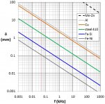
My mind works in SI, so based on your rules (AWG13 is 2 Ohm every 1000 feet, so around 6 Ohm per km) I've searched AWG15 to see if it is 10 Ohm per km (to keep an easier reference in SI) and I've found this:
May I ask you more details on the skin effect at power frequencies?
My mind works in SI, so based on your rules (AWG13 is 2 Ohm every 1000 feet, so around 6 Ohm per km) I've searched AWG15 to see if it is 10 Ohm per km (to keep an easier reference in SI) and I've found this:
AWG American Wire Gauge Diameter and ResistanceResistance:
AWG 15 is 10 mohm/m.
Adding 3 doubles the resistance, and subtracting 3 halves it.
Adding 10 multiplies the resistance by 10, and subtracting 10 it divides by 10.
Diameter:
AWG 18 has a solid diameter of about 1mm
Adding 6 halves the diameter, Subtracting 6 doubles the diameter
Adding 20 divides the diameter by 10, and subtracting 20 multiplies the diameter by 10.
May I ask you more details on the skin effect at power frequencies?
Zintolo,
Great rule of thumb! (I use both metric and imperial, being british and having a odd mix of both systems)
However, I prefer wire gauges in metric! as well as screws and threads!
Great rule of thumb! (I use both metric and imperial, being british and having a odd mix of both systems)
However, I prefer wire gauges in metric! as well as screws and threads!
jhstewart₉;6460420 said:At 20 degrees C, 1000 feet of AW #10 Copper Wire has a resistance of very close to One Ohm. As the wire size decreases (higher number), the resistance doubles for every three numbers up the scale. So #13 wire has a resistance of close to 2 Ohms per 1000 feet. The common ratio is the 3rd root of 2.............1.260, so #11 AWG would be 1.26 Ω per 1000 ft (about 1¼ Ω). And #12 AWG is 1.587 Ω (about 1.6 Ω).
Mmm… not really (technically): 2⅓ is very close to, but not the same as 10¹⁄₁₀, which is what the ratio really is. Originally, the AWG scale was just that… moving 10 gauge numbers resulted in 10× (–10 AWG) or ¹⁄₁₀x (+10 AWG) the cross section area.
Just saying… an older EE.
⋅-=≡ GoatGuy ✓ ≡=-⋅
Me too, I find it easier to be remembered and to get rules of thumb. Well, I have to say that I use it not so often at work, just to design the power supply of boreholes, whilst I have other rule of thumb for water flow in pipings: 2 inch Tri-Clamp pipes contain 2 liters of liquid per meter (then you scale up and down quadratically with the diameter), but rheology differs from electron flow so its resistivity is not linear increasing pipe section and also depends on liquid characteristics (most fruit juices are thixotropic).I prefer wire gauges in metric! as well as screws and threads!
Thank you all elderly users of this forum for all the information you are transmitting to others. In this age of disinformation due to excess of information, your pills of knowledge are manna from heaven.an older EE.
⋅-=≡ GoatGuy ✓ ≡=-⋅
Mmm… not really (technically): 2⅓ is very close to, but not the same as 10¹⁄₁₀, which is what the ratio really is. Originally, the AWG scale was just that… moving 10 gauge numbers resulted in 10× (–10 AWG) or ¹⁄₁₀x (+10 AWG) the cross section area.
⋅
Many older (like me) electrical engineers in the power end of the business keep this in the back of the mind, makes possible quick calculations of voltage drop while in the field without a calculator.🙂...
Skin effect is a factor even at power frequencies for large diameter conductors & long lines. So AC resistance (not inductance) is greater than DC resistance. Less of the cross section of the conductor is in use for AC.
All hard to believe!😱
Just think of AWG in terms of dB and all the calculations you’re used to just work.
But eventually the *voltage drop* gets dominated by inductance as volt-amp-distance gets scaled up, despite the increased AC resistance. Even at secondary distribution levels you need both L and R to calculate drops under load. At 220kV, with the required conductor spacing, inductance almost completely dominates and to a first order even AC resistance can be ignored. Transformer (leakage) inductances tend to be high as well, and the fault current is the open circuit generator voltage divided by the sum of the reactances in the loop. A “small” R won’t change it much.
I’m glad my dumb question elicited an interesting conversation.
Makes me feel less guilty for asking it!
Makes me feel less guilty for asking it!
skin effect at power frequencies?
It's around 8mm at 60Hz, so the copper is electrically wasted if thicker than twice that.
But eventually the *voltage drop* gets dominated by inductance as volt-amp-distance gets scaled up, despite the increased AC resistance. Even at secondary distribution levels you need both L and R to calculate drops under load. At 220kV, with the required conductor spacing, inductance almost completely dominates and to a first order even AC resistance can be ignored. Transformer (leakage) inductances tend to be high as well, and the fault current is the open circuit generator voltage divided by the sum of the reactances in the loop. A “small” R won’t change it much.
I know absolutely nothing about high voltages (the highest I ever used was 2.66 kV), but for normal operation rather than faults, can't you tune out inductive reactance with capacitive reactance to some extent? Ideally you would have to place capacitors in series when you are bothered by series inductance, but with shunt capacitors at small enough intervals (<< lambda/4, so << 1250 km at 60 Hz) you can still approximate a lower characteristic impedance transmission line, like the opposite of the Pupin coils in analogue telephone lines.
By the way, I sometimes see twists in the wiring of three-phase high-voltage pylons (like 150 kV or 380 kV). I've always wondered what those are for, does anyone know?
FULLY answered on the FIRST answer, but no, it had to drift with the wind, including not asked about wirewound resistors, inductance and reaching the dreaded **skin effect** 😱, is there any difference between a 4k and 8k wired in series, and a single 12k resistor?
Will we sink further into resistor *brand* ,*sound*, "transparency" arguments? 🙄
Just curious 😀
Happy
 to all.
By the way, I sometimes see twists in the wiring of three-phase high-voltage pylons (like 150 kV or 380 kV). I've always wondered what those are for, does anyone know?[/QUOTE]
Equalize capacitance of each conductor to ground.
Equalize capacitance of each conductor to ground.
- Home
- Amplifiers
- Tubes / Valves
- Series plate load resistors