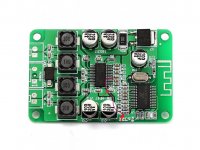
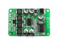
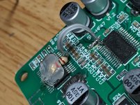
Hello everyone, about two years ago i buyght a tpa3110 bluetooth amplifier board, the sanwu hf-47. The board would be pretty fine if it didn't have an awful background hiss, clearly audible at low volumes; i think that's mainly because the gain is set to the maximum value. Looking at the board and using a multimeter, the two gain pins (pin 5 and 6) of the tpa3110 are connected together to a small capacitor (C20) and to a resistor (R2), which is put between these pins and a pin of the bluetooth chip, which i suppose is responsible of setting the gain by tying the two gain pins high (this would give a 36dB gain according to the datasheet).
I tried unsoldering the resistor and the capacitor, then shorting the capacitor solder pads together, as the other side of the capacitor is connected to ground, and by doing so the gain pins would be shorted to ground, and if i understood right this would set them both to logical 0, thus setting the gain to 20dB. The problem is that by doing this the amplifier doesn't work at all, only the bluetooth part works and pairs fine, but the tpa remains muted/switched off.
I now resoldered the components back in place and the amplifier works just fine, but the background hiss really makes it unpleasant at low volume. Do you have any clue on how to change the gain? Any help is greatly appreciated 🙂
EDIT: The first edited image is wrong! See post #4 for the correct version
Attachments
Last edited:
Are you certain that's where the pins connect to? Did you check with a meter? Running these pins to the Bluetooth chip doesn't make much sense.
What you did sounds correct IF you in reality did what you assume to have done. The TPA3110 chip should continue working with 20dB gain, not be disabled. Please short-circuit the capacitor you mention but else leave both the capacitor and resistor in place. Before testing if you can hear a much lower Bluetooth signal, please check with an Ohm-meter that both pins 5 and 6 are tied to ground and NOT hard-wired to AVCC in any way.
I double checked with the ohm meter and yes, pins 5 and 6 are both connected in the way i said earlier.
I shorted the capacitor and every time i short it (even while the board is playing), the amplifier is muted.
I also figured out why it gets muted, and this is not "my fault": pin 1 and 2 (SD and faultz) are both connected to pin 5 and 6, and consequently if i short the capacitor the mute pin also gets shorted to ground, effectively muting the amplifier, as per datasheet.
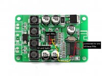
All those PINs are not connected to AVCC in any way, they're connected to one of the bluetooth chip legs through a pcb track on the other side of the board. I assume the BT chip ties high all these pins when there's audio being reproduced, and by doing so it both unmutes the amplifier (which otherwise is put into shutdown mode and is completely silent) and sets the gain to 36 dB. Then, when the audio pauses, the BT chip ties the pins low and mutes the amplifier, and that's how they avoid any power on pop and hiss when nothing is playing; it gets annoying though, because at low volumes the amplifier gets muted frequently when there are silent parts in music, and you can hear it clearly.
So i guess the only solution to change gain is to lift up pins 5 and 6 from their place and connect them to ground (or only one of them, depending on the gain you wish to set), am i right?
Attachments
Last edited:
It seems that the designers have "invented" a kind of noise-gate. Can't you cut the connection between pins 1+2 and pins 5+6 on the board? I can't see this as a successful marriage anyway.
Last edited:
It seems that the designers have "invented" a kind of noise-gate. Can't you cut the connection between pins 1+2 and pins 5+6 on the board? I can't see this as a successful marriage anyway.
Unfortunately the connection is hidden behind the chip itself, there's probably a track going near the power pad which connects them and then comes out from the side. There's nothing on the other side of the board so no luck there. I guess the only way to modify it is by either cutting the legs of the chip or lift them, but that's quite a challenge considering the size of the chip.
You now know the reason for the problems. Unfortunately I know no easy solution. Luckily it is a cheap board. Therefore I discourage use of boards with on-board Bluetooth as they often give problems.
Does my thread help?
My first project with a class-d board was with a TPA3110 with bluetooth board but the BT daughterboard implementation was junk and the designer had made some sort of gate to stop the noise inbetween the BT audio being active. Chermann helped me with gain as well. I also put a blob of solder some pins to get the amp active.
Different board but might help.
TPA3110d2 BT Board Fixes?
You now know the reason for the problems. Unfortunately I know no easy solution. Luckily it is a cheap board. Therefore I discourage use of boards with on-board Bluetooth as they often give problems.
Does my thread help?
My first project with a class-d board was with a TPA3110 with bluetooth board but the BT daughterboard implementation was junk and the designer had made some sort of gate to stop the noise inbetween the BT audio being active. Chermann helped me with gain as well. I also put a blob of solder some pins to get the amp active.
Different board but might help.
TPA3110d2 BT Board Fixes?
Hello, your thread was very helpful even before i opened this one, i used it to understand how the gain is set on the chip, so thank you!
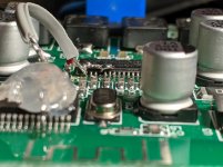
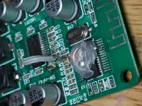
Today i challoenged my soldering skills and modded the pcb. First i managed to lift up the first two pins (SD and faultz) by heating up their solder pads and lifting them with a needle. Then i soldered a wire that goes into a 1000 ohm resistor and then to the pin on the bluetooth chip that mutes/unmutes the amplifier. On the board i removed the capacitor and resistor i previously mentioned and shorted the track to ground where C2 was. With this configuration pins 5 and 6 are still connected together and shorted to ground, while pin 1 and 2 are now separated and controlled by the BT chip; the gain was set to 20dB. The mod worked perfectly,noise was inaudible and muting/unmuting in silent parts didn't happen anymore, because i had to keep the volume much higher on the phone.
The gain, though, was a bit too low for me (the bt chip isn't so powerful), so i decided to go all in and with my soldering iron and some very thin pliers i managed to lift up pin 5 as well, and soldered it to the previously lifted pins 1 and 2. By doing so the gain is now set to 26dB, noise is acceptably low and muting/unmuting doesn't bother me as well (it happens only at barely audible volumes). I am able to make my speakers distort now (not with 20dB gain) but this happens at the very highest volume setting on the phone, so it's perfect for me and my 5 watt speakers that otherwise would start distorting at a lower volume setting. So, in conclusion, it's a win-win as i get to protect the speakers more.
To anyone looking to make the same modification, don't do what i did but just lift up pin 6 and connect it to ground,, this will set the gain to 26dB like my modification but requires only to lift up one pin and remove no components.
I attached pictures of the modification, only the first one shows the 26dB configuration, the other ones were taken with the 20dB one. The resistor glued on the bt chip is a 1kohm, and the capacitor that was onboard was omitted as i don't know its value, but the board still works fine. I unluckily stripped one pcb track (the one connecting the resistor to pin 10 of the bt chip) so the THT resistor is directly soldered to pin 10 of the BT chip.
Also, despite this year being absolute trash, happy holidays to everyone 🙂
Attachments
Impressively well done. SSOP chip-housings are nasty to modify on. Happy New Year to you as well.
Next time, separate BT.
Next time, separate BT.
- Home
- Amplifiers
- Class D
- TPa3110 bluetooth board gain modification - is it possible?