If you want the lowest noise out of this chip you have to set it for lowest gain. Right now its set for the maximum gain of 36dB. The 47k/75k combo should be replaced with 5.6k for first resistor and completely remove the second one. Check the datasheet for details on this. As a side effect this also increases the input impedance.
Modern sources should be good enough with it set on the lowest gain.
Modern sources should be good enough with it set on the lowest gain.
Hello Trileru,
Actually with great respect to you all that's needed is to remove both 75k resistors.
Please see my 3116 page in the link below.
Cheers
Actually with great respect to you all that's needed is to remove both 75k resistors.
Please see my 3116 page in the link below.
Cheers
I was referring to the board in the first post, which is a single chip. I think you have two chips on your pcb?
The correct datasheet setup calls for a 5.6k resistor on the other one. I wouldn't leave the original one and just remove the other.
Check page 14 of the datasheet. There's also a table with the values of input caps for each setting, as increasing the input impedance you can lower the value of the input caps. For 20dB (with only 5.6k resistor for gain setting) you'd need 1.5uF input caps, as the input impedance is 60kohm.
I'm not sure what happens if you keep the 47k resistor instead of the 5.6k recommended one. Could make for all sorts of issues.
The gain is adjusted by input resistors, it works only if you feed with low impedance voltage source. Here, to get maximum NFB, I feed with high impedance current source by this the amp is no more voltage in voltage out but current in voltage out. The internal series resistor provokes voltage drop, higher is value more voltage swing on the collectors. To keep it to minimum, the highest gain is chosen which is 9k, with minimum gain it is 60k, that is 7 times more voltage swing. With TPA3255 it will be 20k.If you want the lowest noise out of this chip you have to set it for lowest gain. Right now its set for the maximum gain of 36dB. The 47k/75k combo should be replaced with 5.6k for first resistor and completely remove the second one. Check the datasheet for details on this. As a side effect this also increases the input impedance.
Modern sources should be good enough with it set on the lowest gain.
Last edited:
You mean you attenuate the preamp swing with input resistors?
The chip has a fixed gain. In your case it's 36dB. You can test this by feeding a signal into your amp, let's say 100mV. With the 36dB of gain from the amp you'll have 6.3V on its output. That is a fixed gain that you can't dynamically alter. Even if you control the input swing with resistors, the chip is always going to have a 36dB gain on that input signal.
What I was proposing was to lower the gain setting of the chip itself, to 20dB, that way any input signal including noise would get a 20dB increase instead of 36dB.
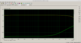
Here are my findings as promised
Attachments
-
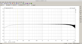 fq_response_loopback_emu0202_att_30dB.png31.6 KB · Views: 282
 -
TPA3118_PFFB_2017_05_14b_SignalGain.asc6.4 KB · Views: 137
-
 tpa3118_stereo_AFE_sch.png108 KB · Views: 194
 -
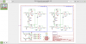
 tpa3118_stereo_2017_06_sch.png131.2 KB · Views: 199
 -
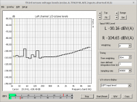 noise_A_TPA3118_AFE_inputs_shorted.png39.2 KB · Views: 138
 -
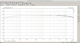
 fq_response_TPA3118_24V_LS_left_no_load_R_comp_330R.png.png35.1 KB · Views: 251
 -
 fq_response_TPA3118_24V_LS_left_10R_load_R_comp_330R.png.png35.3 KB · Views: 238
 -
 fq_response_TPA3118_24V_LS_left_5R0_load_R_comp_330R.png25.2 KB · Views: 252
 -
 FqResponse_TP3118_2BTL_PFFB_right_feeds_left_via_10R.png21.8 KB · Views: 252
You mean you attenuate the preamp swing with input resistors?
The chip has a fixed gain. In your case it's 36dB. You can test this by feeding a signal into your amp, let's say 100mV. With the 36dB of gain from the amp you'll have 6.3V on its output. That is a fixed gain that you can't dynamically alter. Even if you control the input swing with resistors, the chip is always going to have a 36dB gain on that input signal.
What I was proposing was to lower the gain setting of the chip itself, to 20dB, that way any input signal including noise would get a 20dB increase instead of 36dB.
Indeed, if you higher the input resistor from 9k for gain of 36db to 60k for 20db, the output noise, error, distortion gets less attenuated and more correction is applied. Now, imagine you put in series externally more resistance adding to 60k lets say 540k, than instead of the error to be divided by 10 it will be divided by 2 and the noise, distortion is 5 times less. Imagine now that you drive the amp with several megohms current source, the error is no more divided and the noise, distortion is 10 times lower than with minimum gain of 10. This is what makes the amp sublime.
As it is current driven, the switched input resistor doesn't act anymore except provoking voltage swing which generates distortion in the driver. So lower is the input resistor better it is.
Last edited:
On TI you can down load the spice model of TPA3116D2 in Pspice now. Except slave mode all other function are implemented.Here are my findings as promised
Sad that you didn't measure the distortion after extra feedback.
- Home
- Amplifiers
- Class D
- Sublimed TPA3116D2