Hi
quick question from a puzzled amateur...
I've recently finished my first amp build and there is a bit of hum through the speakers so I'm working my way through the various ideas I see in forums such as this in an effort to remove it.
An article on Valve Wizard (Merlin Blencowe) talks about elevated filament voltage and as I have the parts I thought I would test this out.
On the 6.3V filament supply I have a virtual center tap which normally goes directly to ground so I setup the circuit like this which I calculate should elevate the virtual center tap to about 42V

What puzzled me was that the voltage on the B+ side of the 1M resistor was 470VAC but on the other side of the same resistor my DVM reads 0VAC.
I am very new to this so it may well be a simple explanation but I expected to see 42VAC.
Many thanks.....
quick question from a puzzled amateur...
I've recently finished my first amp build and there is a bit of hum through the speakers so I'm working my way through the various ideas I see in forums such as this in an effort to remove it.
An article on Valve Wizard (Merlin Blencowe) talks about elevated filament voltage and as I have the parts I thought I would test this out.
On the 6.3V filament supply I have a virtual center tap which normally goes directly to ground so I setup the circuit like this which I calculate should elevate the virtual center tap to about 42V
What puzzled me was that the voltage on the B+ side of the 1M resistor was 470VAC but on the other side of the same resistor my DVM reads 0VAC.
I am very new to this so it may well be a simple explanation but I expected to see 42VAC.
Many thanks.....
If you want to elevate the heaters, they must be at a DC potential, not AC.
I doubt your hum comes from the heaters unless the pre amp valves are factory rejects and sold as NOS.
If the hum is 100HZ it is main smoothing related otherwise 50HZ will be an earth/ground loop or in the wrong place.
I doubt your hum comes from the heaters unless the pre amp valves are factory rejects and sold as NOS.
If the hum is 100HZ it is main smoothing related otherwise 50HZ will be an earth/ground loop or in the wrong place.
The most practical place to elevate the heater supply center tap is a voltage divider on your power supply bleeder resistor. For instance, if your bleeder resistor is 100k ohms and your plate supply is 470V, you can just add the 10k to the ground side of the 100k. If you simply add a 10k resistor to the existing 100k ohm resistor, the junction of the voltage divider is about 10/110 = .09; .09 * 470V = 42.3V.
If you want to elevate the heaters, they must be at a DC potential, not AC.
My mistake..... 470Vdc on the B+ and all other voltages are DC too.
I'll try again with the circuit drawing....
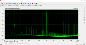
Regarding the hum, I see quite big spikes at 50Hz and 100Hz in an FFT but I've had all of the capacitors out of the PS, tested and even tried with different ones but the peaks don't change.
Last edited:
I believe heaters only need elevation if the cathode is not grounded. Maybe show the amps schematic to get the best advice
If that’s the picture your trying to load then I’m sorry for stating the obvious.
If that’s the picture your trying to load then I’m sorry for stating the obvious.
You did not care to reveal what kind of amp you built, but it may at least use one tube ..
In order to eliminate hum you have to find the main cause first.
What makes you think it is related to the filaments ?
First step : mains frequency or twice this (with many overtones probably) ?
A scope picture will tell us more. But your first picture is invisible.
In order to eliminate hum you have to find the main cause first.
What makes you think it is related to the filaments ?
First step : mains frequency or twice this (with many overtones probably) ?
A scope picture will tell us more. But your first picture is invisible.
A picture of your amps layout and wiring would help,as others have said is your hum 50hz or 100hz? Check and recheck your grounding layout. No signal IP, DMM on your HT set to AC volts , what's the reading?
Pull out the first valve, does hum go?
Andy.
Pull out the first valve, does hum go?
Andy.
I didn't give much away did I. sorry about that.
The amp is a Kegger / Blueglow SE KT88.
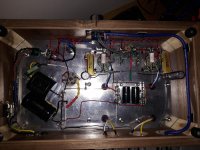
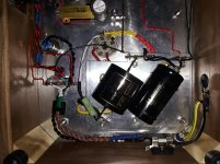
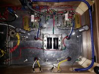
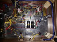
I've attached the schematics, some photos of the build, an FFT trace and the circuit I was testing to elevate the filament supply.
My initial post was about the 0Vdc reading I see on the virtual center tap of the 6.3V secondary when I elevate it. I thought this may be because the CVT is not drawing any current but as I'm still very much in the learning stage I wanted to ask.
From the FFT I'm guessing that the hum is most likely in the power stage somewhere but I don't know it's the filaments. I have tested the filter capacitors and I have spares so I've tried with both sets and there is no change. The choke tests ok at 80Ohms DC resistance (Edcor specify 75Ohms).
I do have some suspicion about the actual PT though (Edcor XPWR033 @ 240V / 50Hz). It has a definite mechanical buzz to it and runs quite hot though I'm not sure if it's too hot. The PT is mounted on grommets to damped the buzz but maybe it's injecting the hum into the B+ in some way (if that's even possible).
Grounding is a ground bus running from the input tube to the KT88's to the PT CT where the chassis gound is located at the first filter cap. The power ground is next to the IEC connector.
All voltages match those on the BlueGlow build. The B+ reads around 50mV (AC) and pulling the first tube makes no difference.
Thanks you all and any thoughts appreciated....
The amp is a Kegger / Blueglow SE KT88.
I've attached the schematics, some photos of the build, an FFT trace and the circuit I was testing to elevate the filament supply.
My initial post was about the 0Vdc reading I see on the virtual center tap of the 6.3V secondary when I elevate it. I thought this may be because the CVT is not drawing any current but as I'm still very much in the learning stage I wanted to ask.
From the FFT I'm guessing that the hum is most likely in the power stage somewhere but I don't know it's the filaments. I have tested the filter capacitors and I have spares so I've tried with both sets and there is no change. The choke tests ok at 80Ohms DC resistance (Edcor specify 75Ohms).
I do have some suspicion about the actual PT though (Edcor XPWR033 @ 240V / 50Hz). It has a definite mechanical buzz to it and runs quite hot though I'm not sure if it's too hot. The PT is mounted on grommets to damped the buzz but maybe it's injecting the hum into the B+ in some way (if that's even possible).
Grounding is a ground bus running from the input tube to the KT88's to the PT CT where the chassis gound is located at the first filter cap. The power ground is next to the IEC connector.
All voltages match those on the BlueGlow build. The B+ reads around 50mV (AC) and pulling the first tube makes no difference.
Thanks you all and any thoughts appreciated....
Attachments
-
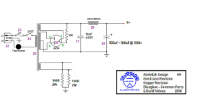 SE-KT88 v6 PS Only - Blueglow - Final Build - No Voltages.png131.6 KB · Views: 282
 -
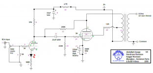 SE-KT88 v6 Amp Only - Blueglow - Final Build - no Voltages.png192.4 KB · Views: 252
 -
 2155.jpg1,016.6 KB · Views: 227
 -
 2156.jpg1,001.5 KB · Views: 186
 -
 2157.jpg1 MB · Views: 184
 -
 100v1+10v1.png41.7 KB · Views: 180
 -
 Untitled.png7.8 KB · Views: 236
Last edited:
Did you wait a couple of minutes for the 470 uF capacitor to get charged?
It probably only ran for a minute or so, long enough for the B+ stabilise.
I'll try again and measure the capacitor as well this time.
Is your main copper bar only connected to the top plate in one spot?
Yes, at the first filter cap. The mounting tags on the tag boards are all unused.
> Yes, at the first filter cap.
You can pick up noise from rectifier current-pulses at the first cap's terminal - try moving the 0V/GND to the last filter cap (100+100µF)
You can pick up noise from rectifier current-pulses at the first cap's terminal - try moving the 0V/GND to the last filter cap (100+100µF)
> Yes, at the first filter cap.
You can pick up noise from rectifier current-pulses at the first cap's terminal - try moving the 0V/GND to the last filter cap (100+100µF)
I think this is already how it's setup unless I misunderstand what you're suggesting.
There is a 4 lug tag strip at the first filter cap where all of the grounds converge. The lugs are all connected together.
Tag 1 - Ground bus & 6.3V virtual center tap
Tag 2 - First filter cap & connection to chassis
Tag 3 - Second filter cap & PT 0V/GND
Tag 4 - Speaker terminals ground
Last edited:
He is running final current through the voltage amplifier stage return. Why not star ground the amp?
Can you expand on this.... I'm not sure what this means.
I understand what a star ground is but not "running final current through the voltage amplifier stage return".
The wire bottom right in the picture is just earthing the metal plate which the RCA and speaker jacks are mounted on to the chassis. The jacks are all isolated.
Imagine your wire to have resistance, any current passing produces a voltage. What happens when a 1mA current and a 100mA pass through the same resistor? The common mistake is to take for granted that once a wire is "grounded" it is free of any voltage.
Maybe first cap and second cap is not clear enough.....
The 10µF neg terminal should connect to the PT's CT.
Then wire 10µF neg terminal to the 100µF neg terminal.
Don't wire anything else to the 10µF neg terminal.
Then, think a while about what painted just said...
Lastly, wire the signal 0V signals to the 100µF neg terminal, all the time thinking about whether you are mixing different signal-currents, or power-currents, in the same wire.
- Home
- Amplifiers
- Tubes / Valves
- Elevated filament supply