Hi Gents ,
I’m designing an OPAMP based preamp for home stereo use.
It will accept multiple inputs driven into R2R volume attenuation , forcing the volume stage to be the fist stage in the chain.
My plan is to use buffer stage right after the R2R to drive the voltage gain stage , possibly running parallel OPAMPs for better THD.
Currently I prefer to use JFET based OPAMP for the buffer stage and send it’s output to a (maybe paralleled) BJT OPAMP.
Was wondering if such configuration of OPAMPs can cause instabilities or performance degradations.
Some design options that I’m considering for your references:
LR based lowpass filtering for the input signal eliminating EMI and RF noise
Overall 6dB gain for 2v output (attenuation for non phono devices at the input)
All OPAMPs will be DC coupled
Current bias on both .. (although it’s possible that having DC filters on the output could eliminate the needs for it)
Possible bootstrapping of the JFET buffer to DC rail
Last edited:
You should probably use the input buffer stage to produce your desired gain and low output impedance for the attenuator. then a unity gain buffer stage after that. place your gain early in the chain to improve SNR.
You will need a pot for every input and output to null out the DC offset. Then in 4 or 8 years when a pot wiper oxidizes and loses contact with the track you will need a new input appliance or power amp input stage.
Op amps with tiny DC offset tend not to have great slew rate or low noise levels for audio. The one obvious low noise plus balence input choice is NE5534, which tends to not be in stock at distributors. You also need an external compensation cap for that one. If you listen to music you didn't record yourself, it has probably been through a dozen coupling capacitors or more. Mastering vacuum tube mixers with >100 db s/n have a capacitors for every tube, plate capacitor.
Op amps with tiny DC offset tend not to have great slew rate or low noise levels for audio. The one obvious low noise plus balence input choice is NE5534, which tends to not be in stock at distributors. You also need an external compensation cap for that one. If you listen to music you didn't record yourself, it has probably been through a dozen coupling capacitors or more. Mastering vacuum tube mixers with >100 db s/n have a capacitors for every tube, plate capacitor.
Last edited:
What does R2R and pampas mean?
Cheers!
sorry , I re-edited. was meant to OPAMPs. stupid auto-correction probably.
R2R - ladder resistor network , relay switched.
thanks
You will need a pot for every input and output to null out the DC offset. Then in 4 or 8 years when a pot wiper oxidizes and loses contact with the track you will need a new input appliance or power amp input stage.
Op amps with tiny DC offset tend not to have great slew rate or low noise levels for audio. The one obvious low noise plus balence input choice is NE5534, which tends to not be in stock at distributors. You also need an external compensation cap for that one. If you listen to music you didn't record yourself, it has probably been through a dozen coupling capacitors or more. Mastering vacuum tube mixers with >100 db s/n have a capacitors for every tube, plate capacitor.
I'm okay with AC coupling. question is , does current biasing still makes sense in that case? I know that controlling current biasing can lower the DC offset , however it obviously adds Johnson Noise , unless it's cancelled on both inputs.
what about mixing JFET for buffer and BJT for gain stage?
You should probably use the input buffer stage to produce your desired gain and low output impedance for the attenuator. then a unity gain buffer stage after that. place your gain early in the chain to improve SNR.
since the R2R circuit is external to the OPAMP , it will be someone difficult to implement such chain.
I can however have the input signal go into the buffer stage , then control the gain stage with the R2R network (externally)
this should still ensure the input stage will be impedance compensated by the buffer stage.
thoughts?
The commercial mixers I've upgraded let the DC offset hang out uncorrected. No offset pots. Even if an electrolytic coupling cap is backwards biased, if the voltage is less than 1 it is not a longevity or sound problem.I'm okay with AC coupling. question is , does current biasing still makes sense in that case? I know that controlling current biasing can lower the DC offset , however it obviously adds Johnson Noise , unless it's cancelled on both inputs.
what about mixing JFET for buffer and BJT for gain stage?
JFET has current noise, BJT has voltage noise. Input structure has to account for these effects for least noise. JFET tends to be used for high impedance inputs like guitar pickups electrometers & PH meters. BJT elsewhere. I'm using BJT ST33078 as a 50* gain input for a MM phono cartridge, where it makes a whole lot less noise than the NJM4558 the mixer came with.
yes , I'm aware of the current vs voltage noise with JFETs and BJTs.
when talking about JFETs for input buffer , it's also the stability of the unity gain that needs to be looked at. I'm curious if it could affected by the R2R or BJT stages which would load it.
regarding your commercial mixers statement , so you're saying that DC coupled OPAMPs will not be an issue for music even when not DC nulled?
i used CD4066's 35 years ago for a 10 bit volume R2R setup. Works great today
I used it to auto fade cassette tape recordings back then. 80db attenuation -100db signal / noise ratio.
if I were to redo it, I would use an Arduino cpu to drive the switches.
Indianajo, I am using a 2SC1815 gain of 10 BJT as the first stage of my phono pre.
I used it to auto fade cassette tape recordings back then. 80db attenuation -100db signal / noise ratio.
if I were to redo it, I would use an Arduino cpu to drive the switches.
Indianajo, I am using a 2SC1815 gain of 10 BJT as the first stage of my phono pre.
Last edited:
All 3 of my commercial mixers have capacitor coupled op amps. Not DC coupled. Peavey PV8 had capacitors between the 3 stages - input, tone control, line drive. The RA-88a has a capacitor between the input/RIAA op amp and the mixer/line drive op amp. Input is DC coupled but since the +input followes the - input direct coupled through 36k to the MM cartridge, negligable current flows. + input is separated from analog ground by a 25 uf capacitor, so the input can follow whatever DC voltage the - input is putting out.
Schematic is in post 5 of this thread: Improving a "Disco mixer" to mid-fi performance
Sounds as good to me now as my "legendary" dynaco PAS2 12AX7 preamp. At 1/20 th the electricity consumption and e-caps last longer than 10 years.
Schematic is in post 5 of this thread: Improving a "Disco mixer" to mid-fi performance
Sounds as good to me now as my "legendary" dynaco PAS2 12AX7 preamp. At 1/20 th the electricity consumption and e-caps last longer than 10 years.
stupid auto-correction
Heh. I've had to add words to my auto-correct dictionary. I got tired of talking about pampas with cascade loaded misfit input stages when I was trying to describe opamps with cascode loaded mosfet input stages. My iThingies are smart enough to share the dictionary across devices, so I only have to edit one dictionary.
My plan is to use buffer stage right after the R2R to drive the voltage gain stage , possibly running parallel OPAMPs for better THD.
Sounds like a good idea. That buffer can be your output driver as well. Depending on the impedance of your R2R ladder, it may be necessary to add a buffer on the input of the volume control as well.
Currently I prefer to use JFET based OPAMP for the buffer stage and send it’s output to a (maybe paralleled) BJT OPAMP.
If you use a modern audio opamp, such as the LM4562/LME49720, OPA1612, OPA1656, etc. you won't have to worry about THD as it's below -140 dBc at line level. You can check the data sheets, but I'm pretty sure some of the OPA... are JFET input.
Was wondering if such configuration of OPAMPs can cause instabilities or performance degradations.
Usually no.
You'll want AC coupling - especially in the phono stage. 60-70 dB of gain in an MC input phono stage will happily gain up a small offset to become a large voltage.
Also, see my comment about using modern opamps. The LM4562 has a worse case offset of 0.7 mV and a typical offset of 0.1 mV.
i used CD4066's 35 years ago for a 10 bit volume R2R setup. Works great today
Howdy fellow Calgarian! Those analog switches / transmission gates are great for general purpose analog switching and - depending on your system requirements - may work for switching audio as well. They do tend to cause a fair amount of THD by modern standards, however, so they would not be my first choice in a low-THD preamp.
Doug Self has an entire chapter devoted to analog switching in his Small Signal Audio Design book. It's a very worthwhile read. The chapter on phono stages provide good insights as well. Small-signal relays with gold plated contacts are hard to beat on THD. That's not to say that there can't be other solutions as well. If memory serves an R2R ladder has the switches connecting to ground, which should open up some options for switch topologies.
Tom
Last edited:
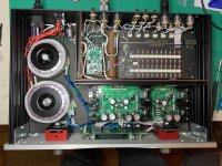
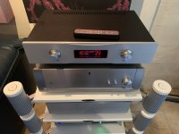
I recently completed a preamp very similar to what you are describing. I used a four channel (balanced stereo) relay-switched attenuator from Khozmo, operated as a shunt attenuator, feeding an op-amp based output buffer using alpha-24 PCBs from AMB Labs.
The alpha-24 is an instrumentation-style design using OPA1612s as input buffers feeding a OPA1632 as a balanced differential amp. The two outputs drive a OPA1611 for single-ended output. I use the balanced outputs for my main amps and the single-ended outputs to drive my subwoofers.
The preamp sounds fabulous - besting my Parasound JC-2.
I also built some projects using boards from Neurochrome, and I don't think you could go wrong either way. The main reason I decided to use the components I did in this preamp is that I wanted to try using Vishay Z-foil resistors for all the signal-path resistors, and also wanted to build the output buffers myself.
Attachments

Last edited:
I DC cascade as many stages as practical. Offsets add up fast. Some circuits (like a bass tone control) vary the DC gain of the circuit depending on control setting and this must be taken into account.
I always put a cap on the input, and then the output, in any line level build. Sometimes you need one in the middle somewhere. Using Jfet input devices mitigates this and allows you to DC cascade more stages.
I always use Nichicon Muse bipolar caps for audio coupling. And I can't emphasize this point enough: electrolytic capacitors properly applied in an audio circuit introduce no distortion of any consequence. (Many commercial designs don't apply them properly! And it's audible) They simply can't if their impedance is negligible compared to the input impedance of the circuit they're coupling. Plus, bipolar capacitors are more linear than traditional electrolytics, because while one leg is charging the other is discharging.
how do you find the muse vs other bipolar caps? I though its lacking some low end , but otherwise very transparent and natural.
I recently completed a preamp very similar to what you are describing. I used a four channel (balanced stereo) relay-switched attenuator from Khozmo, operated as a shunt attenuator, feeding an op-amp based output buffer using alpha-24 PCBs from AMB Labs.
The alpha-24 is an instrumentation-style design using OPA1612s as input buffers feeding a OPA1632 as a balanced differential amp. The two outputs drive a OPA1611 for single-ended output. I use the balanced outputs for my main amps and the single-ended outputs to drive my subwoofers.
The preamp sounds fabulous - besting my Parasound JC-2.
I also built some projects using boards from Neurochrome, and I don't think you could go wrong either way. The main reason I decided to use the components I did in this preamp is that I wanted to try using Vishay Z-foil resistors for all the signal-path resistors, and also wanted to build the output buffers myself.
thanks for sharing. that's a neat display. also how did you get the remote control costumed your way ?
The Khozmo attenuator I used comes with the OLED display and rotary encoders for controlling volume and input selection. Included in the price is an engraved remote control and customized logo displayed on the OLED.
I have one set of balanced outputs that are AC coupled, but this is to provide some high-pass filtering since my main speakers (GR-Research NX-Oticas) roll off at around 45Hz and I use powered stereo servo subs to handle the bottom couple of octaves. The caps provide a gentle roll-off of the signal to the main amps and allow easier blending with the subs.
The other outputs are DC coupled all the way through and my DC offset at the speakers is less than 100mV when I'm using the DC coupled preamp outputs. But, of course, this will depend on your sources which may have more DC offset.
how do you find the muse vs other bipolar caps? I though its lacking some low end , but otherwise very transparent and natural.
You have to set your poles low. I go for 1.6 or 3.2 Hz.
That "lacking some low end" might be because your circuit design lacks the tubbiness that an improperly applied coupling capacitor can and will introduce. Remember, your input cap is in series with the output cap of your CD player etc.
The difference in bass between my preamp and my "substitute" preamp (a Sony unit from a 90s era "separates" package) is absolutely startling. You wouldn't think a preamp would affect bass but if you don't do it right it most certainly will. The Sony is really bass forward and boomy in comparison. You would think this could only happen when switching speakers, but apparently not.
Many of our ears have grown accustomed to the deficiencies in consumer grade equipment. When we hear articulate bass instead of booms we think it's dry. When we hear clear midrange instead of garbled mush we think it lacks sparkle.
Claims that coupling caps "smear" the signal at all frequencies don't add up, whether you look at the physics or whether you listen for yourself. All I hear is my circuits getting cleaner sounding and quieter. What's really missing is all the distortion introduced by operating a capacitor in a manner that accentuates its nonlinearities.
Audio has specific requirements that make it different in some ways than other linear circuits. Anyone that builds digital control circuits uses dirty grounds all day long and it makes not a bit of difference in the performance of the circuit. We all know what would happen if we took that approach to audio.
A capacitor CAN´T "lack low end" by itself.how do you find the muse vs other bipolar caps? I though its lacking some low end , but otherwise very transparent and natural.
An **RC** circuit can, of course, it will have some crossover frequency, which the capacitor does NOT.
Of course, self DELUSION knows no limits.
Sadly 🙄
The Nichicon MUSE ES-series is sonically transparent to the best of my measurement capability (Audio Precision APx525 + a few tricks). I've made circuits with THD below -140 dBc using those caps. But, yeah, as Fast Eddie said, place the lower pole in the 0.2-2 Hz range to avoid any audible reduction in amplitude at 20 Hz.
Tom
Tom
- Home
- Source & Line
- Analog Line Level
- OPAMP based preamp design considerations ..