Hi guys,
I have to make a 200 kHz 10W AB amplifier with 20 ohm load.
I did a basic 3 stage SMD bipolar transistor audio AMP with Sziklai output stage and +/- 24V supply with no very success. This amp has good band but instable DC operating point, it oscillates from 0V to 0.2/0.8 and sometimes to 1V so the current switch only in a side of the two supply and it doesn't work. When the operating point is stable (very rare) the AMP works but shows a bad parasitic oscillation in the positive half. Probably this is due to the Sziklai output configuration.
I don't know why the DC point is unstable, while in simulation is few mV away from 0V.
Anyway my request is simple, with this frequency as target, should I find a new approach, a new amp configuration? Try a MOS based AMP or a completely new architecture, when can I read something about amplification at that frequency?
With a common audio AMP is not difficult extend band until 200 Khz (with some distortion but I'm not interested in) but I'm finding this DC instability so I don't know if try a new better scheme or change totally.
Hi guys,
I have to make a 200 kHz 10W AB amplifier with 20 ohm load.
I did a basic 3 stage SMD bipolar transistor audio AMP with Sziklai output stage and +/- 24V supply with no very success.
You need slew rate at least 15V/uS to get 200kHz full power bandwidth. The easiest way is use CFA topology. But you can try this simple amplifier: Emprit amplifier.
Without complete specifications, it is difficult to determine what you want. In class AB, at a frequency of 200 kHz, the efficiency of GNFB decreases. Crossover distortion increases. Application in the output stage of a single EF is possible. You can try the virtual battery bias diamond buffer.
????????? ????????? - ?????? Zarathustra

????????? ????????? - ?????? Zarathustra
Last edited:
Hi guys,
I have to make a 200 kHz 10W AB amplifier with 20 ohm load.
I did a basic 3 stage SMD bipolar transistor audio AMP with Sziklai output stage and +/- 24V supply with no very success. This amp has good band but instable DC operating point, it oscillates from 0V to 0.2/0.8 and sometimes to 1V so the current switch only in a side of the two supply and it doesn't work. When the operating point is stable (very rare) the AMP works but shows a bad parasitic oscillation in the positive half. Probably this is due to the Sziklai output configuration.
I don't know why the DC point is unstable, while in simulation is few mV away from 0V.
Anyway my request is simple, with this frequency as target, should I find a new approach, a new amp configuration? Try a MOS based AMP or a completely new architecture, when can I read something about amplification at that frequency?
With a common audio AMP is not difficult extend band until 200 Khz (with some distortion but I'm not interested in) but I'm finding this DC instability so I don't know if try a new better scheme or change totally.
DC instability and oscillations are topology related... Maybe you could get away with some line driver ic with simple power follower stage in the loop.
My little cascaded diamond does reasonably well at 200KHz.
https://www.diyaudio.com/forums/sol...eap-low-thd-10w-amp-tip41c-4.html#post5307265
https://www.diyaudio.com/forums/sol...eap-low-thd-10w-amp-tip41c-4.html#post5307265
15-20W Class AB Audio Amplifier
A design with class-A performance but reduced thermal dissipation
by J. L. Linsley Hood
http://www.keith-snook.info/wireles...orld-1970/15-20W Class AB Audio Amplifier.pdf
A design with class-A performance but reduced thermal dissipation
by J. L. Linsley Hood
http://www.keith-snook.info/wireles...orld-1970/15-20W Class AB Audio Amplifier.pdf
15-20W Class AB Audio Amplifier
A design with class-A performance but reduced thermal dissipation
by J. L. Linsley Hood
http://www.keith-snook.info/wireles...orld-1970/15-20W Class AB Audio Amplifier.pdf
Have a look at Fig. 5. Power output/frequency characteristics. @ 200KHz.
Replace BJT with 5200/1943. The circuit will provide the required bandwidth.
Reduce the 390 pF capacitor in correction. Change Zobel. Shunt the output capacitor with a foil.
Reduce the 390 pF capacitor in correction. Change Zobel. Shunt the output capacitor with a foil.
Last edited:
What is the intended load you have to drive?
Inductive? (a coil) ,
Capacitive? (piezo), etc.
Doubt it´s a plain speaker and even if so, t those frequencies they behave very differnt than at audio frequencies.
Lots of questions.
Inductive? (a coil) ,
Capacitive? (piezo), etc.
Doubt it´s a plain speaker and even if so, t those frequencies they behave very differnt than at audio frequencies.
Lots of questions.
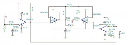
I can help you design one, even in two stage. You must specify what distortion you expect. Lm3886 has 100khz PBW, A pair in bridge should give over 300khz for 10W 20ohm.
I found in my achieves an example, it gives clean 30Vp 200khz,22W

and max 300khz

I can elaborate the circuit in split or single supply.
Attachments
Last edited:
Use the LT1210 with an additional stage on transistors and get a very good low power amplifier with a high slew rate and a wide gain range of 1 MHz
Last edited:
Without problems. use shifting the midpoint of the opamp power supply or removing the signal from the opamp power pinsFor 10w/20ohm 20Vp is needed, LT1210 is 15Vp.
A little background: this amp should drive an acoustic trasducer (antenna) at 200 kHz more or less. I'm not interested in THD, distortion or noise, the amp will send power in few pulse, not a clean signal. Thermal and DC stability and bandwith are important.
I can't use integrated circuit, only SMD components and TH for power end transistors, so every suggestions about IC are unusable but thanks anyway. Other schemes I've seen looks a bit complex.
Here you can see my first circuit that exibits DC instability, there are some errors but DC instability is even a mistery for me.
I'm thinking to make a PCB with a revision of that circuit, more focused, but I'm worried about DC instability will be still there, so I hope to find, with your help, the right way to get a good amp not too complex but working.
I can't use integrated circuit, only SMD components and TH for power end transistors, so every suggestions about IC are unusable but thanks anyway. Other schemes I've seen looks a bit complex.
Here you can see my first circuit that exibits DC instability, there are some errors but DC instability is even a mistery for me.
An externally hosted image should be here but it was not working when we last tested it.
I'm thinking to make a PCB with a revision of that circuit, more focused, but I'm worried about DC instability will be still there, so I hope to find, with your help, the right way to get a good amp not too complex but working.
An externally hosted image should be here but it was not working when we last tested it.
A pulse amplifier (key) is needed to amplify the pulses. Why do you need DC stability?
Load - ultrasonic piezo emitter? Capacitive. What then is 20 ohm?
Load - ultrasonic piezo emitter? Capacitive. What then is 20 ohm?
To amplify 200 kHz pulses, a bandwidth of up to 2 MHz is needed 🙁
Zero Feedback Impedance Amplifiers
Zero Feedback Impedance Amplifiers
This website is dedicated for audio, your request is not sufficiently specified. Is your frequency/amplitude is fix or variable? Maybe a 200khz switched, filtered square wave is sufficient, or class C + 200khz resonator.
This AMP should be AB class, it has to drive an acoustic underwater antenna, with fixed amplitude, and narrow bandwith into 200 kHz (190/210 something like that). When I say pulse I don't mean a square wave, so we have to consider a sinusoidal signal, a simple case.
For DC stability I mean 0V into the output without input signal. Actually with the first schematic I posted, this DC point is instable, I don't know why.
For DC stability I mean 0V into the output without input signal. Actually with the first schematic I posted, this DC point is instable, I don't know why.
- Home
- Amplifiers
- Solid State
- 200 kHz AB amplifier