Do you want sand in your amp? 😀 Ok back to the serious questions.
I have an tube design, that uses 6SN7 cascodes in parallel. More details here

Currently the system uses a +300.0.-300 (600V) configuration, with a folded cascode I'm hoping that can be dropped perhaps to ±240V or even less, 150.0.150 for example - providing better options for the power supply and reducing heat noise effects etc. The other benefit is the reduction in heater and real estate.
I understand JFETs and MOSFETs each have their own issues (here is a good thread detailing some) although I'm leaning towards a JFET implementation due to the flatter response curve.
Any thoughts/suggestions?
I have an tube design, that uses 6SN7 cascodes in parallel. More details here
Currently the system uses a +300.0.-300 (600V) configuration, with a folded cascode I'm hoping that can be dropped perhaps to ±240V or even less, 150.0.150 for example - providing better options for the power supply and reducing heat noise effects etc. The other benefit is the reduction in heater and real estate.
I understand JFETs and MOSFETs each have their own issues (here is a good thread detailing some) although I'm leaning towards a JFET implementation due to the flatter response curve.
Any thoughts/suggestions?
Last edited:
the term folded cascode in the mos implementation refers to an Nch and Pch combination.
as tubes are only Nchannel devices,the folded cascode term does not apply to tubes.
the spice schematic shows only two 0 - 300V stages in a differential mode, despite the drawing style
as tubes are only Nchannel devices,the folded cascode term does not apply to tubes.
the spice schematic shows only two 0 - 300V stages in a differential mode, despite the drawing style
the term folded cascode in the mos implementation refers to an Nch and Pch combination.
as tubes are only Nchannel devices,the folded cascode term does not apply to tubes.
the spice schematic shows only two 0 - 300V stages in a differential mode, despite the drawing style
Correct that these are two 300V stages, however the reason one is -300 is to provide a reduced potential across the PP coupling cap.
Another thread: Folded/shunt cascode differential question
Last edited:
I just spotted your point - the 300 is no longer -300. Good point lol. Serves me right for thinking about this at 330am.. I remember changing this previously because it was a PITA with 600V etc..
Still I may look at this - see if I can fit into 150V.
Still I may look at this - see if I can fit into 150V.
Last edited:
Ok - just looked at this again - it is -300, have a look at the centre supplies - those are -300. (they're set 300 but the - terminal)
So back to my plan 🙂
So back to my plan 🙂
The circuit as drawn is a Series cascode.
"Folded" cascode is a term used in the IC industry for complementary cascode, as bassreflex noted. The "folded" part comes from the physical layout of elements on the IC die - so it is doubly misleading for a valve design, and that's why I always use "Shunt Cascode" instead....
A Shunt Cascode is identified by having a current-source to force-feed the cascode node, with the cascode device (usually PNP) directing the 'overflow current' to the output.
The 6SN7 is not a great candidate for any of this: it does not like the vertical load-line of a cascode, and good quality parts are very expensive. High-gm frame-grid TV valves are much better, because the gm translates directly into higher gain - at least with a Shunt Cascode it does.
The low gm of 6SN7 also makes a fairly poor job of the upstairs (cascode-voltage) position. Having a solid grip of the cascode voltage makes or breaks a cascode design. The high gm of bipolar transistors is easily heard in series or shunt cascode stages, and a voltage regulator of the highest quality is needed to really do it justice, if large output swings are required. My latest Shunt Cascode board has an all-discrete regulator with a 120dB closed-loop AF bode, and even that is not overdoing it!
The circuit as drawn is a Series cascode.
"Folded" cascode is a term used in the IC industry for complementary cascode, as bassreflex noted. The "folded" part comes from the physical layout of elements on the IC die - so it is doubly misleading for a valve design, and that's why I always use "Shunt Cascode" instead....
A Shunt Cascode is identified by having a current-source to force-feed the cascode node, with the cascode device (usually PNP) directing the 'overflow current' to the output.
The 6SN7 is not a great candidate for any of this: it does not like the vertical load-line of a cascode, and good quality parts are very expensive. High-gm frame-grid TV valves are much better, because the gm translates directly into higher gain - at least with a Shunt Cascode it does.
The low gm of 6SN7 also makes a fairly poor job of the upstairs (cascode-voltage) position. Having a solid grip of the cascode voltage makes or breaks a cascode design. The high gm of bipolar transistors is easily heard in series or shunt cascode stages, and a voltage regulator of the highest quality is needed to really do it justice, if large output swings are required. My latest Shunt Cascode board has an all-discrete regulator with a 120dB closed-loop AF bode, and even that is not overdoing it!
With a mu of 100 - 6SL7 may be better. I will have a look at trying that, and I have thought around the shunt (I found that researching) and model that too. [the 6SL7 seems to work better - thank you!]
The reason for the 'complex' is designing around focusing on reducing noise.
Last edited:
Every device adds noise.
True. If a signal exists within noise, duplicating a device increases signal power but averages noise power.
I've used the same techniques in Astro-photography - take multiple photos then combine them - the signals (stars, planets, nebulae etc) are strengthened and the noise which is a distribution, is averaged. There's a lot of signal processing that carries between the two fields. Using paralleled allows you to cancel out common signals (including common noise).
How about: none of the above.
How about using a pair of bipolar junction transistors to implement the folded cascode?
They would be (high voltage) PNPs. Their emitters would connect to the input tubes' plates. These two emitter+plate nodes would be pulled up by identical resistors to Vtoprail. The two PNP bases would be connected together and tied to the folded-cascode bias DC voltage. And the two PNP collectors would shoot differential currents downward towards the bottom rail, exactly as NickKUK desires in post #1 of this thread.
How about: none of the above.
How about using a pair of bipolar junction transistors to implement the folded cascode?
They would be (high voltage) PNPs. Their emitters would connect to the input tubes' plates. These two emitter+plate nodes would be pulled up by identical resistors to Vtoprail. The two PNP bases would be connected together and tied to the folded-cascode bias DC voltage. And the two PNP collectors would shoot differential currents downward towards the bottom rail, exactly as NickKUK desires in post #1 of this thread.
Mark, thank you - I'll look into these. Initial research I'd found a comparison that had indicated BJTs typically were more noisy than JFET/MOSFET so I'd not continued to evaluate them.
The noise of a suitable PNP (Try the ZETEX/Diodes Inc ZTX558) will be completely lost in the noise derived from the valve. MOSFETs are not quieter, and JFETs are no use in high voltage cascodes.
Sorry to be negative but the design seems to be overly complicated. If low noise is the object of the exercise using valves is a bit mad, why not just use a HV opamp like the LT6091 - LTC6091 Datasheet and Product Info | Analog Devices or the ADHV4702 - ADHV4702-1 Datasheet and Product Info | Analog Devices
Andy.
Andy.
How about: none of the above.
How about using a pair of bipolar junction transistors to implement the folded cascode?
They would be (high voltage) PNPs. Their emitters would connect to the input tubes' plates. These two emitter+plate nodes would be pulled up by identical resistors to Vtoprail. The two PNP bases would be connected together and tied to the folded-cascode bias DC voltage. And the two PNP collectors would shoot differential currents downward towards the bottom rail, exactly as NickKUK desires in post #1 of this thread.
Your thinking something like this? (just using the MJE350 as I have that in the LTSpice library rather than it being the best for the job). FFT of about 200mS run time.

The noise of a suitable PNP (Try the ZETEX/Diodes Inc ZTX558) will be completely lost in the noise derived from the valve. MOSFETs are not quieter, and JFETs are no use in high voltage cascodes.
+1
I use a cascode of ZTX558 and BC557 and I have been very satisfied with their performance for low currents (<10mA)
I wouldn't rely on FFT from simulations though, they aren't very credible
Last edited:
Here is an amplifier with a "Long Tailed Pair" differential input, which uses PNP transistors to create a folded cascode. I present the original schematic (NSC LM6161) and a modified version showing thermionic valve LTP
_
_
Attachments
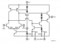
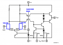
Here is an amplifier with a "Long Tailed Pair" differential input, which uses PNP transistors to create a folded cascode. I present the original schematic (NSC LM6161) and a modified version showing thermionic valve LTP
Thank you again! This is what I'm currently playing with, and it's starting to look reasonable - with just 320V rather than ±320V.

MOSFET Folded Cascode
This is what I would do to lower the rail voltage.
I like FETs, but you can of course change the NMOS to tubes, and PMOS to PNP.
There are 500V PMOS around, e.g. FQP3P50.
And R14,15 can be high voltage current sources such as IXCP10M45S.
Cheers,
Patrick
.
This is what I would do to lower the rail voltage.
I like FETs, but you can of course change the NMOS to tubes, and PMOS to PNP.
There are 500V PMOS around, e.g. FQP3P50.
And R14,15 can be high voltage current sources such as IXCP10M45S.
Cheers,
Patrick
.
Attachments
Using a current mirror CCS on the plate too allows the B+ requirements to be dropped to 200V - the voltage swing is small from the 6SN7, however the current swing is enough that given a ZTX558 the current can then be used to create a voltage swing through the 7500ohm resistor.

It's a little hybrid for purists now but I think this is starting to look decent.
The only issue is reducing the reistance means you suffer from the difference in phase causing an DC offset. I'm still looking at ways to reduce this at the LTP level rather than adjust the bias of the output tubes.
It's a little hybrid for purists now but I think this is starting to look decent.
The only issue is reducing the reistance means you suffer from the difference in phase causing an DC offset. I'm still looking at ways to reduce this at the LTP level rather than adjust the bias of the output tubes.
Last edited:

- Home
- Amplifiers
- Tubes / Valves
- Folded Cascode - Tube, JFET or MOSFET?