Hello,
Can please someone clarify two things with regards to IST coupling in the following common-cathode configuration.
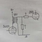
1. Do I need grid leak here? I've seen various opinions on whether it's better to have IST staring at ~infinite grid or rather have a fixed load of, say, 100k.
2. Do I need a grid stopper here? Or would IST secondary DCR serve the purpose to prevent oscillation/low pass?
Thanks,
Igor.
Can please someone clarify two things with regards to IST coupling in the following common-cathode configuration.
1. Do I need grid leak here? I've seen various opinions on whether it's better to have IST staring at ~infinite grid or rather have a fixed load of, say, 100k.
2. Do I need a grid stopper here? Or would IST secondary DCR serve the purpose to prevent oscillation/low pass?
Thanks,
Igor.
Attachments
Very rarely is not having a "stopper" mounted close to the socket lug a good idea.
What characterizes an "ideal" load of the IST's secondary varies from specimen to specimen. Ringing must be avoided.
What characterizes an "ideal" load of the IST's secondary varies from specimen to specimen. Ringing must be avoided.
Hello,
Can please someone clarify two things with regards to IST coupling in the following common-cathode configuration.
1. Do I need grid leak here? I've seen various opinions on whether it's better to have IST staring at ~infinite grid or rather have a fixed load of, say, 100k.
2. Do I need a grid stopper here? Or would IST secondary DCR serve the purpose to prevent oscillation/low pass?
Thanks,
Igor.
If the transformer is chosen carefully with the actual driver tube those resistors are not needed and will be better.
When you see grid resistors on the next stage or even RC networks that's because the transformer is less ideal or not really meant for that driver tube.
The DCR of the transformer is usually good enough for stopper purpose, being in the 150-500R range.
One good rule when using interstage is that you design around the transformer and not around a specific driver tube.
Last edited:
This is not a grid leak resistor (transformer's secondary DCR serves as one). This resistor, together with driver tube plate resistance, dampens the HF resonance of the transformer. Sometimes you need one, sometimes you don't - it depends on the transformer and the driver tube.1. Do I need grid leak here? I've seen various opinions on whether it's better to have IST staring at ~infinite grid or rather have a fixed load of, say, 100k.
Transformer's secondary is useless as a grid stopper - it's located too far from the grid pin. Whether you need the separate resistor or not, depends mostly on the output tube - low-mu power triodes usually don't require one, RF pentodes usually do.2. Do I need a grid stopper here? Or would IST secondary DCR serve the purpose to prevent oscillation/low pass?
Grid stopper located right at the tube socket, the need for a shunt resistor across the secondary will be determined by the quality/performance of the actual IT used.
I have not needed a shunt resistor with the Lundahl or Monolith Magnetics ITs I have used in my own designs. Of the two I prefer the MM, but at a significant increase in cost.
I have not needed a shunt resistor with the Lundahl or Monolith Magnetics ITs I have used in my own designs. Of the two I prefer the MM, but at a significant increase in cost.
It's a good idea to load the IT from the POV of safety as well. I've seen arcing between g1 and ground pins of the output tube (where the IT secondary outputs are) when a driver tube is in overdrive and cuts off. Loading the secondary removes the arcing.
It's a good idea to load the IT from the POV of safety as well. I've seen arcing between g1 and ground pins of the output tube (where the IT secondary outputs are) when a driver tube is in overdrive and cuts off. Loading the secondary removes the arcing.
That's a bad transformer, sorry.
You will also see some interstage transformers that specify that a series resistor and capacitor go across the secondary, and I would absolutely not ignore that.
If you have a really nice 10K interstage transformer and a very low impedance driver tube (say a 6C45PI), then the loading resistor may not be all that helpful.
If the load the IT presents to the driver tube is not that high relative to the plate impedance of the driver tube itself, you may end up with some HF/LF rolloff as the IT impedance varies with frequency. A loading resistor will mitigate this issue.
You will also see some interstage transformers that specify that a series resistor and capacitor go across the secondary, and I would absolutely not ignore that.
If you have a really nice 10K interstage transformer and a very low impedance driver tube (say a 6C45PI), then the loading resistor may not be all that helpful.
If the load the IT presents to the driver tube is not that high relative to the plate impedance of the driver tube itself, you may end up with some HF/LF rolloff as the IT impedance varies with frequency. A loading resistor will mitigate this issue.
The network across the secondary (be it just R or RC) is normally specified if 1) it's nearly impossible to get smooth response 2)source impedance is not within a specified range. But one could accept peaking because normally amplifiers with IT do not use feedback or at least the IT is not included in the loop.
Lower impedance is not guarantee of absence of peaking. It really depends on the balance of leakage inductance and capacitance which in turn are determined by design. Because the cat can be skinned in different ways you cannot tell a priori. That's why I wrote earlier that one should first pick the transformer he likes, not a generic one, and design the driver stage around it.
IT's are not like OPT's that thanks to their consistent step-down are a lot more forgiving in this department.
If you take a good and rather common transformer like the Lundahl LL1660 for example, SE:SE in ALT S or ALT T connection it's recommended for 14K or 3.5K source impedance, respectively. Higher source impedance will make lower frequency response worse but if you use lower impedance tube it clearly says that peaking might occur. You can reduce peaking by adding resistors at the secondary and this sentence also means that having resistors in that position is a compromise respect to having the ideal source impedance......
Last edited:
So, what does the response of the LL1660 look like with and without a loading resistor? (assuming the driving impedance is roughly 1/3 of the intended primary impedance)
Peak or no peak at higher frequency without or with load. The one without resistor might appear more extended but that is a consequence of not damping the resonance. If the peak is well outside the audible range is not necessarily a problem.
At low frequency of course lower impedance is better but the transformer is already good with the suggested source impedance. Improving on that might not bring much benefit.
At the same time the manufacturer specification does not take into account a real power tube. Any power tube has input capacitance! So that might serve as compensation and you might be able to use lower source impedance without adding anything to the secondary. This is why I say you build the circuit around the transformer and the easier way is that you start with few candidates for the driver stage and do not get stuck on one type.
Last edited:
Thanks everyone for your input, I'll definitely add the grid stopper and will check experimentally whether I actually need the shunt resistor.
The common theme I noticed is "compatibility" between IST and driver tube. Are there any specific things to look at apart from generic
- driver tube should have as small plate resistance as possible
- transformer should have as much inductance as possible?
For example given the 5687 tube with rp=2.5kΩ and Hammond 126C transformer with L=106H and 10K:10K nominal impedance, would they be a reasonable pair?
That's a bad transformer, sorry.
I think it's not the transformer quality discussed here, it's common collapsing magnetic field of an inductor physics.
Or you meant transformer resistance to breakdown voltage? A 1:1 should be pretty immune to this.
I think it's not the transformer quality discussed here, it's common collapsing magnetic field of an inductor physics.
Or you meant transformer resistance to breakdown voltage? A 1:1 should be pretty immune to this.
I would be surprised if such a big issue would have gone unnoticed for 100 years.
Having grid resistor on the power tube has nothing to do with safety. It has never been a problem for properly made transformers. The power tube is a FINITE load (a small grid current is always present in either direction, in both no signal and any modulation level conditions) and a grid resistor is not necessary.
Last edited:
My mistake might be the overstating of saying it might be an issue. But I've observed the phenomena with my own eyes multiple times. And cannot see a reason why it wouldn't happen.
It shouldn't be a problem, especially for 1:1 interstage transformers thought, where a magnetic collapse should result in equal voltage differences between primary and secondary layers.
It shouldn't be a problem, especially for 1:1 interstage transformers thought, where a magnetic collapse should result in equal voltage differences between primary and secondary layers.
If the transformer is Bifilar, with the 2 wire windings side by side . . .
Then the voltage breakdown issue is worst case, when the primary is at a relatively high B+, and the secondary is at a high negative value for Fixed Bias.
Example, B+ + 350V, and fixed bias at -80V.
The side by side insulation has to withstand |350V| + |80V| = 430V
Or, if you prefer +350V (-) -80V = 430V
- Home
- Amplifiers
- Tubes / Valves
- Interstage transformer coupling