This amp doesn't seem to like that I changed the driver transistors. Both channels give this waveform around 1VAC on the speaker loads during power test. The same thing happens with the amp unloaded. Last time I had a similar issue raising the value of the VAS capacitor fixed it. I'm not sure which cap that is in this circuit. What should I try?
Someone had already changed a couple of the drivers, I put in a set of MJE15032/33. Outputs are original.
Someone had already changed a couple of the drivers, I put in a set of MJE15032/33. Outputs are original.
Attachments
Did you read the schematic information available on hi-fi engine ?
Quote -
"in both the driver and last stages ---SPECIAL PNP and NPN transistors of PRECISELY MATCHED characteristics are employed .
Left and right channel circuits are NOT combined on one circuit but are separated into two monophonic amplifiers .
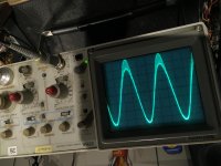
Your upside down oscilloscope showing the bottom trace proves that point --overhang/unbalance , if you scroll down far enough you will see the BJT type numbers of the drivers --you need to adjust this to balance the signal out .
Adjusting a compensation capacitor value (upping it ) can remove HF oscillation but can have negative effects on bandwidth etc but not a case of imbalance .
Quote -
"in both the driver and last stages ---SPECIAL PNP and NPN transistors of PRECISELY MATCHED characteristics are employed .
Left and right channel circuits are NOT combined on one circuit but are separated into two monophonic amplifiers .
Your upside down oscilloscope showing the bottom trace proves that point --overhang/unbalance , if you scroll down far enough you will see the BJT type numbers of the drivers --you need to adjust this to balance the signal out .
Adjusting a compensation capacitor value (upping it ) can remove HF oscillation but can have negative effects on bandwidth etc but not a case of imbalance .
Correct me if I'm wrong, but MJE15032/33 are like 8 A parts and seem way oversized as drivers in this (by modern standards) moderately powerful amp where they are run at (sub-average) 4 mA tops. There isn't any published fT(Ic) graph but I won't be surprised if they're rather sluggish like that, hence your stability issues. IMHO you would be much better off using some medium power jobs like KSC2690/KSA1220 or perhaps MJE243/253, with mechanical adaptations to the heatsinks as required... finding suitable drivers in TO-220 probably is an exercise in futility at this point.
IMHO both the drivers and the outputs are running quite lean in this amp, which is not helping matters. (Nominal output bias current is just 22 mA, drivers are running at ~3.7 mA. More typical for something half its output power.) I'd chalk this up to the sheer age of this design, i.e. lack of experience back in 1973, and/or possibly thermal considerations. I would suggest:
1. Make sure that the bias diode (STV4H - 21, 22) tracks the die temperature of the transistor it's mounted to as quickly as possible - might need some extra thermal compound, not exactly sure how it's attached stock. (This guy has clamped it to the heatsink vs. the TO-3 socket (?) but I am not necessarily convinced that this is an improvement for thermal tracking.)
2. Replace 150 ohm driver emitter resistors by 91-100 ohm.
3. Replace 0.5 ohm / 5 W output emitter resistors by either 0.33 ohms or 0.22 ohms (or something else in this range like 0.27 or 0.24 ohms - should be comparable to the existing ones, low inductance preferred), depending on how generously sized the heatsink is. The idea is aiming for the same bias voltage setting, which obviously corresponds to a higher current the smaller the resistor is.
4. Set bias.
Driver and output bias actually are fairly independent, so you could e.g. change just driver current if you wanted to.
Should you still have issues even with a more sensible choice of driver transistor and increased current, the dominant pole seems to be provided by C9 + Q3/Q4 junction capacitance.
I have KSC2690/KSA1220 and MJE243/253 on hand, I can try either.
The picture was the right side up then it got flipped during upload. I had the issue on another site too.
The picture was the right side up then it got flipped during upload. I had the issue on another site too.
Okay it works with the MJ243/53. Sweet.
Ft of this part is 40Mhz. Originals were 35. The MJE15032/33 I used first were 30.
The Ft of the KSC2690 was several times higher, thought trying the ones that were closer first was most sensible.
I have a similar issue with a bose 1801 to figure out when I pull it out of the box again.
Ft of this part is 40Mhz. Originals were 35. The MJE15032/33 I used first were 30.
The Ft of the KSC2690 was several times higher, thought trying the ones that were closer first was most sensible.
I have a similar issue with a bose 1801 to figure out when I pull it out of the box again.
Yeah, but the fine print is extremely important in this case. fT is highly dependent on collector current and parasitic capacitance (die size). MJE15032 is given with >30 MHz @ 500 mA, while MJE243 is given with >40 MHz at 100 mA. You might find that at the same low current, their fT differs by a factor of 5 or so.Ft of this part is 40Mhz. Originals were 35. The MJE15032/33 I used first were 30.
I actually wasn't able to turn up any fT for the original drivers, but they're 800 mA parts so they wouldn't have been that big for sure.