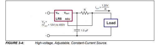
I dont know why but there is almost no info about the LR8 regulator...
Its essentially a LM317 but works up to 450V and does up to 10mA.
Pretty much enough for any 12AX7 contraption even a phase inverter.
There are three versions: TO92,TO252(DPAK),TO243AA(SOT89)
The TO92 can do the least power dissapation at only 0,74W
TO243(SOT89) does 1,6W
TO252 does up to 2,5W
I intend to add a pass transistor at the output really extending the current and dissapation capabillity of the contraption and also taking the feedback from the emitter so that the voltage is absolutely stable. I intend to replace every RC filter in every one of my old radios by this since the radios I own have quite the severe humm problem at high gains.
My other usecase will be to regulate voltages within a tube ampliffier. I have a upcoming 100W KT88 amp project in which I will be using this regulator to regulate the HV for the phase inverter and the preamp tube and also the negative bias voltage for the KT88's. Good stuff.
Try it out I sure will in two days in my radios.
And its pretty cheap aswell.
Datasheet https://www.tme.eu/Document/49ed538122efa3e11e59182b05d3cd61/lr8.pdf
Have a look at : Dynaco PAS4 klonIll totally check that out.
There is both dynaco's schematics and roy's with the changed powersupply.
Actually there are many articles about how to use this regulator with a pass device for higher amperage.
I use it with a IRF830 as the pass element in a preamp with 4 6SN7s and as a screen regulator for 4 6L6GC tubes in a parallel push pull amp.
Here is a link from an article in 2009 that shows how to use it with a TIP50 for the pass transistor. I used a mosfet in place of the TIP50.
https://antiquewireless.org/wp-cont...te_filter_choke_or_field_coil_replacement.pdf
LR8N3 is discussed in Art of Electronics #3. It can't be that quiet as the reference voltage is gained up Vout = Vref *( 1 + R2/R1) + Iadj * R2
Very useful device, however. You can peel off a low voltage for maintenance functions of a switch-mode supply, you can use it with a suitable pass transistor to regulate screen voltage of an output stage..
Looking for a quiet HV regulator ? -- Jan's new edition of the T-Reg, or Tomchr's using the LT3080.
... It can't be that quiet as the reference voltage is gained up Vout = Vref *( 1 + R2/R1) + Iadj * R2
If it's anything like the 317 internally, you should be able to bypass the adj terminal with a small cap so the ripple doesn't get amplified.
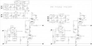
I've been using them in all of my recent phono pre-amplifier designs over about the past 3 years, I LPF them and feed the filtered HV to the gates of high voltage high current mosfets, works very well for higher current applications.
If it's anything like the 317 internally, you should be able to bypass the adj terminal with a small cap so the ripple doesn't get amplified.
Bypassing the ADJ pin improves PSRR and reduces noise -- the tradeoff is that it results in a deterioration of transient response -- this should be a minor issue in Class A phono stage.
I've been using them ... I LPF them and feed the filtered HV to the gates of high voltage high current mosfets, works very well for higher current applications.
What is “LPF them”? I would like to try this for a regulated screen supply. Could you draw a schematic and post the photo, please, please!
I did that LM317 / pass FET 25 years ago for the whole B+ in two Dynaco MKIIIs I used to own. Sold them to someone in Quatar, used USPS to ship and (I assume) they actually made it. I included to original chokes and rectifier tubes so the buyer could restore the original circuit.
Never had an issue with it, after who knows how many power cycles, being left on while away for an entire weekend... Heat sunk to the steel chassis, the whole amp would get plenty hot.
Never had an issue with it, after who knows how many power cycles, being left on while away for an entire weekend... Heat sunk to the steel chassis, the whole amp would get plenty hot.
What is “LPF them”? I would like to try this for a regulated screen supply. Could you draw a schematic and post the photo, please, please!
LPF = Low Pass Filter - to get rid of H(igh)F(requency) noise.

LPF = Low Pass Filter - to get rid of H(igh)F(requency) noise.
Exactly, I set the LF corner at a few fractions of a Hz which also has the benefit of bringing the B+ up in a nice gentle manner over a few seconds.
I have drawn up a quickie that I will be running everywhere from now on.
(Yes I am aware im taking the feedback from the emitter of the transistor and its perfectly fine and above all I also have now a hopefully more stable output which is not linearity dependant of the transistor (TIP50))
(Yes I am aware im taking the feedback from the emitter of the transistor and its perfectly fine and above all I also have now a hopefully more stable output which is not linearity dependant of the transistor (TIP50))
Attachments
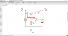
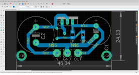
You could add pads for rectifier diodes and a filter cap (or 2 plus pads for a coil), 2 extra mounting holes and a PCB mount heatsink. All this can come very handy in some situations. You definitely want a protection diode over the IC! I don't think the feedback should be taken from the emitter but that is your choice. The SMD resistors will have to be selected for maximum allowable voltage. Probably TH resistors are a more versatile and safer choice.
https://antiquewireless.org/wp-cont...te_filter_choke_or_field_coil_replacement.pdf
https://antiquewireless.org/wp-cont...te_filter_choke_or_field_coil_replacement.pdf
Last edited:
The SMD resistors will have to be selected for maximum allowable voltage like those that are sued in the situations. Probably TH resistors are a more versatile and safer choice.
I was about to make the same comment but you beat me to it 🙂 High voltage SMD resistors are not common.
- Home
- Amplifiers
- Tubes / Valves
- Regulating high voltage (up to 450V) has become as easy as a LM317!