To get rid of the last bit of power supply hum. I have some luck using a serial LC circuit, tuned for 100 Hz.
Hum at the speakerconnector output is reduced with more than 25%, I’m now getting less than 1.5 mV instead of 2 mV.
I’m currently looking for a miniature choke / coil of 10H for this circuit. I need minimal current flow so I’m looking for a miniature choke / coil. The Hammond / Triad chokes are for min. 50 mA and quite big.
Any suggestions for smaller chokes?
Regards, Gerrit
https://www.latout.nl/The primary inductance of an old table radio OT holds probably enough self inductance for your purpose. L'atout has (had) small current chokes from Stoet: www.latout.nl AE Schagen did them as well, about 5cm high.
Both 1.5 mV and 2 mV hum levels are quite audible as I have experienced. The difference is very audible too. Therefore I want to kill all the hum, where I think anything below 1 mV is quite acceptable.
So I still have work in progress and I take this step by step. Of course I check the hum with a spectrum analyzer, so I can very well see the difference on both 50 and 100 Hz..
Regards, Gerrit
So I still have work in progress and I take this step by step. Of course I check the hum with a spectrum analyzer, so I can very well see the difference on both 50 and 100 Hz..
Regards, Gerrit
Most of my amplifiers have less than 100uV hum.
That is good enough for me.
However, for anybody who has very sensitive Headphones, 100uV is not low enough.
I design my power supply filters specifically so that they do not resonate at 1X, 2X, 3X the Power Mains frequencies.
Works for me.
Be careful when testing hum with a device that is plugged into the power mains, and your amplifier is also plugged into the same power mains.
That is the safe way to do it.
But . . . often there is a power mains, to amplifier, to test equipment ground loop current. That ground loop current causes a very small voltage across the shielded cable's ground conductor.
The spectrum analyzer measures that as if it was output hum, when it is only the ground loop hum.
I often used special transformers to break the power mains ground loop. Both the amplifier and the spectrum analyzer were grounded together, via the power mains.
But, the shielded coax from the amplifier output went to the special isolation transformer, and then from the isolation transformer to the spectrum analyzer input.
Success, now the measured hum level was the actual output of the amplifier, not a measurement of the ground loop hum.
Last edited:
Gerrit, can you provide some more detail please.To get rid of the last bit of power supply hum. I have some luck using a serial LC circuit, tuned for 100 Hz.
Eg. have you installed a series LC in place of an inductor in a CLC type filter after the rectifier - that circuit would not pass DC current.
Or have you installed a C in parallel across the L in a CLC type filter, such that the L and parallel C are tuned for twice the mains frequency (ie. aka a ripple trap filter)?
Ciao, Tim
Hi Tim,
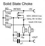
The series LC is between the high voltage rail and ground. The default DC filtering is C-Gyrator-C. If I would have a “real” inductor, I could indeed use a C in parallel, but I have a MOSFET instead.
Regards, Gerrit
The series LC is between the high voltage rail and ground. The default DC filtering is C-Gyrator-C. If I would have a “real” inductor, I could indeed use a C in parallel, but I have a MOSFET instead.
Regards, Gerrit
Gerrit, is this for an SE amp where B+ ripple will transfer to the speaker?
Have you been able to confirm that a B+ with much lower ripple also achieves much lower speaker hum - eg. by using a temporary additional filter or filter stage that eg. achieves 10-20dB B+ ripple reduction? That type of test would remove any risk that speaker hum has another significant hum ingress path than just B+ ripple.
Have you tweaked the gyrator/FET circuit to a practical end where no more 100Hz attenuation can be achieved, and would you be able to expand on what you have done?
I'd expect that a smaller inductor for the LC filter would also have a similarly larger ESR and that may end up limiting the shunt notch ability.
Ciao, Tim
Last edited:
Hi Tim,
The first stage using a 6SN7 is Aikido topology. Second 6SN7 is balanced stage, final tubes are KT150 in Push Pull. I also use some sand (phase shifting, KT150 drivers) and 10M90S CCS’s.
I’ve tried the addition of another MOSFET Gyrator today, without any positive effect on the residual hum. I have no idea yet how to tweak the gyrator for more 100 Hz. attenuation. See schematic diagram attached. I used a 1000 VDC 8A MOSFET instead of the IRF820 because my PSU has 600 VDC (regulated).
Regards, Gerrit
Attachments
Is there always more voltage across the Gyrator than the required burden voltage that the Gyrator has to have?
Consider the ripple voltage that is applied to the Gyrator.
Minimum voltage during the ripple cycle, to the Gyrator, and required output voltage from the Gyrator, Versus the burden voltage of the Gyrator.
If not, then either get a Gyrator with a lower burden voltage, or use a . . .
Actual Choke.
Just my $40 Choke, that has a very low "burden" voltage (not my 2 cents).
Gerrit, I'm only a little way in to setting up an e-choke myself, so at the moment I can't be confident in advising if any modifications could benefit. There are a few circuits being used, including Tentlab commercial offerings, and design notes from WW and people like Quinn and Merlin. Where did you get your e-choke from?
As 6A3sUMMER has advised, if you have a scope and can set up a safe probe for the B+ supply, then the waveform shape may indicate if the e-choke is operating nominally - but I guess abnormal operation is more likely to occur during output stage operational limits (like just before and after on-set of clipping).
You may be able to temporarily disconnect the output stage from earlier stages, such that only the output stage operating at idle is contributing to speaker side hum, and compare that with normal amp hum level to see if you have multiple hum contributors.
How are you measuring the speaker side hum level? It can be worthwhile to use a test configuration for benchmarking any tweaks you make, such as just use a resistor load, and use a suitable rms meter for accurate absolute level measurement, and a spectrum analyser for relative assessment of hum harmonics.
Last edited:
- Home
- Amplifiers
- Tubes / Valves
- DC filtering with LC serial circuit