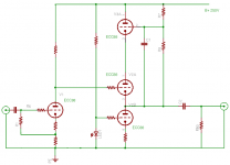
A few years ago I completed a Vacuum State SVP as my backup phono preamp from schematics on the VSE website. This sounds very satisfying (almost as good as my RTP3!), but I would like to lower the line stage gain, as this is too high for my system. I already achieved some reduction from the original version by replacing the 6922 in the voltage amplifier stage with a 5687, and then dropping the cathode resistor from 2K2 to 820 ohms to push the current back to 6mA, but I would like to reduce it further – ideally halving it.
Joe Rasmussen (the original designer of the SLCF line stage in the FVP) suggests a clever way to do this here: this involves increasing the cathode resistor, but then inserting a CCS in parallel with it to restore the net cathode current back to the design value.
Joe draws a nominal JFET circuit, but doesn’t recommend a specific model of JFET. What combination of parameters would make a device most suitable for this application, given that there is 5V at the cathode, and the CCS needs to pass (say) 3mA? I have plenty of 2SK170bl, 2N5457 and BF245C in my JFET box.
Thanks,
Alex
Last edited:
2SK170 is lowest noise.
Source resistor allows you to adjust the CCS current.
Gate stopper can be, say, 100R.
Patrick
Source resistor allows you to adjust the CCS current.
Gate stopper can be, say, 100R.
Patrick
Thanks, Patrick. What I am really looking for is a suggestion as to which device would give the highest impedance and most linear CCS, but would still work with the limited 5V headroom.
Alex
Alex
I would use 2SK246 ( = 2SK208 ) myself.
Very low "Early effect", hence high impedance.
Constant Current Source (CCS) For Audio Applications
Circuit or schematic for current source of 7.5mA
2SK208 is available from Mouser.
Patrick
Very low "Early effect", hence high impedance.
Constant Current Source (CCS) For Audio Applications
Circuit or schematic for current source of 7.5mA
2SK208 is available from Mouser.
Patrick
JFET devices are Ohmic for the first few Drain to Source volts.
That means they are low impedance there.
Look at the Drain curves to find one that comes out of the Ohmic region at a very low
Drain to Source voltage.
Unfortunately, many of those that do, also have Low IDSS currents (lower than 6mA).
Adding a current sense resistor in the Source to lower the current of a medium IDSS JFET, takes away part of the already low Drain to Source voltage.
This might be a loosing battle.
I tried many times to find a suitable JFET for some cathode circuits.
It seemed like I always needed to have a negative supply to make it work properly.
Depending on the circuit parameters, I have used a JFET, LM317, LM334, TIP41C, a more modern NPN (can't remember the number), and a 2N3053 NPN.
.... there is 5V at the cathode
Alex
Plenty for the degenerated 2SK246.
Patrick
.
Attachments

In my guitar amps I use another trick to get the same result: I use an higher Rk that I refer to a negative voltage.
This way I avoid to add the cap at the input of the stage and I reduce the gain of the stage while keeping the same idle point.
It will have more local current feedback.
This way I avoid to add the cap at the input of the stage and I reduce the gain of the stage while keeping the same idle point.
It will have more local current feedback.
EUVL,
Mona has a very good idea!
With a JFET,
The Ohmic region ends at about 2.5V, depending on how much current you want.
But, you have to add 0.2V to 1.6V to that across the Source sense resistor.
That means you have 2.7V to 4.1V Burden Voltage.
With 5V on the cathode . . .
That does not allow for the cathode voltage to swing very far, it will put the JFET into the Ohmic region with only a small signal at the tube grid.
If anybody insists on using a current source in this application, then this might work better . . .
I think a Bipolar NPN with a very low saturation voltage (0.1V), and the base at the voltage of an LED (~1.7V), will have a burden voltage of about 1.1V.
Far better than most JFETs.
I have never had to use a negative supply to get enough range out of my current sources.
They were used in cathode coupled phase splitters, and in output tube self inverting push pull stages.
Sometimes I used a choke as the current source, and a series resistor to adjust the quiescent current.
Careful, a 5 Henry 200mA choke that works as a choke input B+, at 120Hz full wave rectification, but will not do 200mA at 20Hz.
And a 20 Henry 100mA choke that works as a choke input B+, at 120Hz full wave rectification, but will not do 100mA at 20Hz.
Because of the raised DC voltage at the grid, I would have to use a coupling cap at the input, which is why I have never used the circuit that Mona showed.
But it is the simplest solution, and a very good solution.
I just do not like the charging current, and I do not like the dis-charging current to be reflected back to the signal source.
In my opinion, the charge current (at power up) and discharge current (at power down), are the Only disadvantage of Mona's circuit.
And, there are good ways to deal with that (a whole different thread).
Last edited:
In my guitar amps I use another trick to get the same result: I use an higher Rk that I refer to a negative voltage.
This way I avoid to add the cap at the input of the stage and I reduce the gain of the stage while keeping the same idle point.
It will have more local current feedback.
That was one idea I considered. In fact my power amp has a regulated -200V supply precisely for the large resistors on the tails of the LTPs.
Unfortunately the SVP (unlike the RTP3) doesn't have a negative supply, and since the PSU is outboard it would be awkward to provide one.
Alex
Last edited:
Alex, you can get a -9Vdc from that -200Vdc.
You said 3 mA, that means dissipating 600 mW.
That's not a big amount.
You said 3 mA, that means dissipating 600 mW.
That's not a big amount.
In my opinion, the charge current (at power up) and discharge current (at power down), are the Only disadvantage of Mona's circuit. And, there are good ways to deal with that (a whole different thread).
And these ways don't make this solution less simple?
Alex
Alex, you can get a -9Vdc from that -200Vdc.
You said 3 mA, that means dissipating 600 mW.
That's not a big amount.
No, the -200V is in the power amps. Different boxes.
Alex
Plenty for the degenerated 2SK246.
Patrick
That's looking promising. To get 3mA, if I read the curves properly, we want Vgs=-0.5V, and for this we need 167R under the source. This would leave a healthy 4.5V across the FET.
Alex
If you rectify the first tube's heater voltage, the result approximately 8.5V.
This negative voltage, and the required 5V cathode voltage are enough for simple CCS.
This negative voltage, and the required 5V cathode voltage are enough for simple CCS.
Alex M,
All things are equally simple, some things are more equally simple.
The beauty and simplicity of a circuit is up to the beholder.
The problem of using a coupling cap, the charge and discharge currents are often overlooked by a few people.
I wanted people to be aware of the problem.
Best to know the problem, before harming a solid state signal source output stage; or harming a very fine grid wire or frame grid.
And using a negative supply can potentially cause the same problems . . .
harming a solid state signal source output stage; or harming a very fine grid wire or frame grid.
I remember one instance where both 12AX7 grids were destroyed. What a surprise to the user.
Alex M,
Agreed.
Yes, 0.5V bias, and 3mA, looks good.
Swing from 4.5V down to 2.5V (peak swing of 2V). That should give a large swing on the ECC88 plate.
Test the JFET first. No two JFETs match the curves, sometimes can be quite far off from those curves. Lots of manufacturers show at least 2 sets of family curves, one for a larger IDSS JFET, and one for a smaller IDSS JFET, of exactly the same part number.
Hand selection of parts is not always fun.
Last edited:
The problem of using a coupling cap, the charge and discharge currents are often overlooked by a few people.
I wanted people to be aware of the problem.
Best to know the problem, before harming a solid state signal source output stage; or harming a very fine grid wire or frame grid.
And using a negative supply can potentially cause the same problems . . .
harming a solid state signal source output stage; or harming a very fine grid wire or frame grid.
I remember one instance where both 12AX7 grids were destroyed. What a surprise to the user.
I think that's a really good point. I've always been suspicious of the potential for serious harm to the solid-state parts in in hybrid circuits from transients. I've encountered this both in shunt regulators for HT, where the performance deteriorated over the course of a few months, and in a hybrid active crossover of my own design, where I blew several JFETs. I trust Allen and Joe's expertise in the VSE preamps I have built (and have had no problems of this kind whatsoever in these over ten years), but I wouldn't design a hybrid circuit myself again.
What you say about possible damage to valve grids surprises me, but I wouldn't rule it out.
In this case, I am reasonably confident that a JFET on the cathode is unlikely either to be harmed or to induce harm anywhere else. I may be proved wrong, of course...
Alex
Alex M,
Agreed.
Yes, 0.5V bias, and 3mA, looks good.
Swing from 4.5V down to 2.5V (peak swing of 2V). That should give a large swing on the ECC88 plate.
I wondered whether CD input might overload the CCS, but remembered that in my SVP I slugged down the line inputs by about 6dB to compensate for the crazy gain structure of the VSE preamps, so this shouldn't be a problem.
Test the JFET first. No two JFETs match the curves, sometimes can be quite far off from those curves. Lots of manufacturers show at least 2 sets of family curves, one for a larger IDSS JFET, and one for a smaller IDSS JFET, of exactly the same part number.
Hand selection of parts is not always fun.
I did hand-select a large batch of 2SK170s a few years ago, so I know what is involved!
I'll start looking for a decently priced and reliable source of 2SK246 (hopefully before the portcullis slams shut on our little island nation on 31 December).
Alex

Thanks to all for your suggestions and an interesting discussion. I have ordered a handful of 2SK246, and I'm looking forward to experimenting over the seasonal break.
Alex
Alex
- Home
- Amplifiers
- Tubes / Valves
- Choice of JFET for cathode CCS