Note that the LSK489 and LSJ689 are available as dual monolithic JFETs as N-channel and P-channel versions, respectively. These devices have lower transconductance than the LSK389 and correspondingly higher noise, but considerably less capacitance.
Cheers,
Bob
Cheers,
Bob
I know the approach (the diodes are AC bootstrapped with a copy of the input signal) and, to my experience, it works fine as long as you can get dual matched jfets (which are not exactly available today, other than the LSK389). Otherwise, the common mode distortions will dominate. I don't know how to apply the same principle to an op amp, it might be possible, but would be certainly more complicated and dubiously better than the bridge distortion cancellation above.
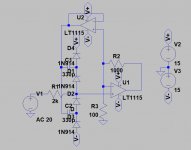
I hope this better illustrates the idea, using an opamp to buffer the inverting input. The opamp is a trivial addition today. The other parts are pretty garden variety as well. You would want to use an opamp with a low input C modulation (e.g. OPA1656)
Attachments
Note that the LSK489 and LSJ689 are available as dual monolithic JFETs as N-channel and P-channel versions, respectively. These devices have lower transconductance than the LSK389 and correspondingly higher noise, but considerably less capacitance.
I doubt the LSK489 jfet's will cut it in this case. LSK489 has Ciss=4...8pF and Crss=3pF, while the original NEC uPA61 dual jfet has Ciss=2.5...5pF and Crss=0.5...1.5pF (datasheet attached). These are definitely unobtanium, but Interfet does somenthing that may work, the IFNU421, IFNU422, IFNU423 devices, they are noisier though (20nV/rtHz) compared with the uPAs (8nV/rtHz). And cost $20 a pop @Mouser...
Attachments

Last edited:
I hope this better illustrates the idea, using an opamp to buffer the inverting input. The opamp is a trivial addition today. The other parts are pretty garden variety as well. You would want to use an opamp with a low input C modulation (e.g. OPA1656)
Did I say I need further clarifications? Otherwise, I'm counting the parts and don't see how this is simpler compared to the diode bridge cancelling, also why it would work better?
The depletion mosfets in the schematic I posted are only a nice way to implement a current limiting, they could be replaced with a 3kohm resistor (matching the feedback resistor value).
Have you experimented this yourself? I don't think the performance can be evaluated by simulation.
How fast does this protection need to be? I wonder if you could use a low C TVS and then some other mechanism to switch in/out for a sustained overvoltage.
Apologies to Jan, we should probably move this to another thread.
Apologies to Jan, we should probably move this to another thread.
Last edited:
Thought about, considered something like https://m.littelfuse.com/~/media/el...fuse_tvs_diode_array_sp3010_datasheet.pdf.pdf, but never tried in practice.
Enough fast so the input stage survives, I would think 😀. 10's of uS may not be good enough... Also depends on the design scope, if the AR can be used for tubes or SS only. That is, it has to survive 500V or 100V input.
Enough fast so the input stage survives, I would think 😀. 10's of uS may not be good enough... Also depends on the design scope, if the AR can be used for tubes or SS only. That is, it has to survive 500V or 100V input.
This may be another option for TVS:
https://www.infineon.com/dgdl/Infin...N.pdf?fileId=5546d462503812bb0150854d5b4e4ca3
Clamping voltage is high but low leakage and high working voltage.
https://www.infineon.com/dgdl/Infin...N.pdf?fileId=5546d462503812bb0150854d5b4e4ca3
Clamping voltage is high but low leakage and high working voltage.
TVS Diodes-It depends on what you are trying to protect against. They are designed for static discharge currents which are high voltage modest current (2-5A) and very short. If the source is a high power amp, which could be as much as 100V with lots of available current, you need the series current limiting to work with whatever your using to clamp. Pretty much any commercial opamp will have internal protection but won't handle a lot of current. The TVSS diode will handle 2A peak but for 8 uS. Its continuous rating would be whole lots lower and that would need to handle a continuous overload (at least until the autorange shift ranges). The depletion mode fets look to be a great idea as long as the normal RDSon is low enough to not limit the noise floor.
syn08- I misunderstood you which is why I tried to illustrate the idea better, showing an implementation with just opamps. Its not better or necessarily worse. Depending on the application it may be an easier fit. A simulation for distortion below 100 dB is wishful thinking. It needs to be built and tested to verify anything in practice.
syn08- I misunderstood you which is why I tried to illustrate the idea better, showing an implementation with just opamps. Its not better or necessarily worse. Depending on the application it may be an easier fit. A simulation for distortion below 100 dB is wishful thinking. It needs to be built and tested to verify anything in practice.
TVS Diodes-It depends on what you are trying to protect against. They are designed for static discharge currents which are high voltage modest current (2-5A) and very short. If the source is a high power amp, which could be as much as 100V with lots of available current, you need the series current limiting to work with whatever your using to clamp. Pretty much any commercial opamp will have internal protection but won't handle a lot of current. The TVSS diode will handle 2A peak but for 8 uS. Its continuous rating would be whole lots lower and that would need to handle a continuous overload (at least until the autorange shift ranges). The depletion mode fets look to be a great idea as long as the normal RDSon is low enough to not limit the noise floor.
syn08- I misunderstood you which is why I tried to illustrate the idea better, showing an implementation with just opamps. Its not better or necessarily worse. Depending on the application it may be an easier fit. A simulation for distortion below 100 dB is wishful thinking. It needs to be built and tested to verify anything in practice.
Yes, I was thinking of for protection for ESD and similar. I guess there really is no way to switch fast enough to make it adequate alone, even with a SSR.
Fuses can work but mean active intervention to fix. Not a great solution but better than a pile of fried parts or a fire. SSRs are not fast enough. The test waveform rises to peak in 8uS and falls in around 20uS. The current can persist for 100 uS. This is representative of a lightning strike. A static discharge from a person would be much faster rise but less current. However continuous overload needs much different protection.
A simulation for distortion below 100 dB is wishful thinking. It needs to be built and tested to verify anything in practice.
Amen.
If anyone thinks the statement above is not screamingly obvious, I recommend you do (a lot) more lab work.
...Apologies to Jan, we should probably move this to another thread.
Given the "Auto" part of the AutoRanger with the corresponding inevitable overrange, this discussion is highly applicable to the thread, and thank you all for diving in!
So far I have only used the AutoRanger for line-level testing but I can imagine the difficulty clamping a transient when testing amplifiers without damage to the unit.
Howie
> the original NEC uPA61 dual jfet has Ciss=2.5...5pF and Crss=0.5...1.5pF
MMBF5484, 2SK366 ?
I know they are not duals.
Patrick
MMBF5484, 2SK366 ?
I know they are not duals.
Patrick
I understand if you don’t want to disclose, but are you using a circuit like the depletion mode current limiters with 2x LND150 or similar to handle overload?
No I use a 50mA fast fuse with a series R.
Jan
I hope this better illustrates the idea, using an opamp to buffer the inverting input. The opamp is a trivial addition today. The other parts are pretty garden variety as well. You would want to use an opamp with a low input C modulation (e.g. OPA1656)
A weakness in this scheme is that the overload energy is dumped into the power supply. You probably will use a series regulated supply which cannot absorb any reverse current, so the supply will just rise as high as the overload voltage, with possibly catastrophic effects downstream.
Jan
If the IDSS is tolerable, BSP129 or similar can replace LND150 with much lower Rds(On).
Rds(on) is not an issue here; the only condition is 2*Rds(on)+R101 to match R102 (the op amp feedback resistor) value, this is where the minimum distortions occur (and why THD depends on the source impedance). But those BSP129’s have much larger non linear Crss, which is not good, its effect is not compensated.
Rds(on) is not an issue here; the only condition is 2*Rds(on)+R101 to match R102 (the op amp feedback resistor) value, this is where the minimum distortions occur (and why THD depends on the source impedance). But those BSP129’s have much larger non linear Crss, which is not good, its effect is not compensated.
Ah, forgot to check the capacitance curves. The total ~2k resistance of the LND150s can be unfortunate if you were expecting low source impedances and use a low noise bipolar op-amp. Not really a problem if you have OPA1656 or OPA827/828 or something out front.
Not really a problem if you have OPA1656 or OPA827/828 or something out front.
...which is what I am using 😀.
Guys, should this not be a separate thread on dummy loads rather than in the autoranger thread ?
I can ask the mods to make that happen.
Jan
I can ask the mods to make that happen.
Jan
- Home
- Design & Build
- Equipment & Tools
- Autoranger for soundcards