I would like to use my audio interface to trigger a mains relay, as soon as the audio interface is turned on. Unfortunately, the interface turns on electronically, as opposed to using a mechanical switch. (I need to hold a button for 3 seconds to turn it on. Annoying but c'est la vie).
Therefore, I figured using the S/PDIF output of the audio interface to trigger the mains relay, by cascading two relays: one relay triggered by the S/PDIF output, which in turn triggers the mains relay.
So with the audio interface turned on and nothing playing, I measured the S/PDIF output on the scope and Vmin and Vmax are around -700mV and 500mV respectively, yielding appx. 1.2Vp-p and about 4mV Vac.
Unfortunately, I reckon 4mV is too low for triggering any kind of relay.
For raising the voltage, I looked at level shifting, but I it's problematic because as demonstrated by the Vmin/max, S/PDIF is a differential signal which makes things trickier, and besides, as far as my limited knowledge goes, I think level shifting needs a higher base voltage anyway.
Finally I thought about amplifying the S/PDIF signal with a MOSFET but I've no experience with those and I've no idea how to go about it.
So I'm kinda stuck right now, and would appreciate your help 🙂
There is no steady state DC voltage on the SPDIF signal that you can use for triggering. You can use an Arduino to trigger a relay when it recognises input high for one pulse at highest sample rate, or less. It will work with SPDIF, though your transmitter needs to have second output, or you need to build a SPDIF relay with a buffer.
Another possibility is the WM8804 (?) which can 'de-jitter' your signal and provide status toggle on a hardware pin, that can be used to trigger a relay using a suitable latching circuit.
A signal shifter is a definite possibility, see the consumer-professional level shifters that convert the 500mV signal to TTL level.
Depending on your interface there may be multiple options to derive a sense signal without resorting to any of the above.
Phantom power is an option, if you don't want to crack it open. If you can open it up, you'll have many more options of deriving a sense signal.
Thank you for your reply!
Phantom power is a great idea! But unfortunately all of my XLRs are in use.. perhaps I could use a splitter/adapter for some kind?
I prefer not to use an Arduino for this.
Concerning the level shifter, I searched and search and searched before posting this and couldn't find anything that supported voltage below 1V. Do you have anything on your mind?
I'm reading now the datasheet for WM8804
Last edited:
Here's a ready-made product:
S/PDIF Level Converter Kit
Here's a schematic of one such, you have to scroll all the way down to the Appendix:
S/PDIF Digital to Analogue Converter
Note the output is still a pulse, not a steady DC voltage so your switching circuit will need to stay latched after it is triggered once. I would use a low-power SCR with an optocoupler to trigger the gate. This would need a power cycle to turn off though.
Amazing - I was looking for just a schematic like that! It just didn't occur to me to search for "coax to ttl". You're a genius!
Have you any idea why, in the TwistedPear circuit, they're using a transformer on the input from the coax? For isolation probably? And then there's that capacitor in front of it to block any DC from entering, right?
Now concerning the connection to the relay, I understand what you mean. Probably something like below will not work, because as you said, the signal is a pulse?
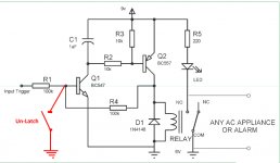
Latch with a push-button un-latch function (no need to cycle the 9V DC)
Attachments
Last edited:
Have you any idea why, in the TwistedPear circuit, they're using a transformer on the input from the coax?
Pulse transformer provides proper impedance matching and should ideally be used at both ends of a SPDIF connection to maintain integrity. Unfortunately an unbalanced signal like consumer SPDIF doesn't benefit. I suspect it's there because someone thought it might be a good idea to stick it in there. It isn't always so.
Now concerning the connection to the relay, I understand what you mean. Probably something like below will not work, because as you said, the signal is a pulse?
No it won't. Post #6 is a good example of one that will. I only worry about needing 0.6V minimum to trigger the input, whereas the SPDIF signal spec allows for a 0.5V minimum. You can convert it to TTL first, that will definitely work.
Just a note, tapping a digital signal is not usually a great idea if you're not passing it through a buffer first. I would much rather use something like this:
Benchmark XLRF to 2 XLRM "Y" Adapter for Analog Audio - Benchmark Media Systems (you can make this yourself). If you are only using it to trigger (not actually drive the relay) it should be fine as long as your mic or source can handle phantom power.
I need to post a correction, in the circuit in #6 when logic 0 is at input, the circuit will unlatch.
What does it mean to "drive" the relay (as opposed to trigger)? This is probably just my internal English processor failing 😀...If you are only using it to trigger (not actually drive the relay)...
There a problem lies though. All of the preamps on the audio interface are occupied by outboard gear. I'm not sure they will survive a 48V strike through the outputs 😀XLRF to 2 XLRM "Y" Adapter ... it should be fine as long as your mic or source can handle phantom power.
Would a capacitor each on pins 2 and 3 be enough to block the phantom power?
Thanks for the insight. If it's not essential then I'll leave it.Pulse transformer provides proper impedance matching and should ideally be used at both ends of a SPDIF connection to maintain integrity. Unfortunately an unbalanced signal like consumer SPDIF doesn't benefit. I suspect it's there because someone thought it might be a good idea to stick it in there. It isn't always so.
Will kindly expand on that? I don't really understand what it means in practiceJust a note, tapping a digital signal is not usually a great idea if you're not passing it through a buffer first. I would much rather use something like this:
Latch with a push-button un-latch function (no need to cycle the 9V DC)
Thanks for the circuit! However, whether I go with phantom power or with S/PDIF, I would like the relay to engage and remain engaged on the first signal, and then disengage when I turn the power off.I need to post a correction, in the circuit in #6 when logic 0 is at input, the circuit will unlatch.
What does it mean to "drive" the relay (as opposed to trigger)? This is probably just my internal English processor failing 😀
Trigger is a sense signal, drive is the current through the relay itself. Many relays have 48V coils so it might be tempting to use phantom power to actually power the relay, which you shouldn't.
There a problem lies though. All of the preamps on the audio interface are occupied by outboard gear. I'm not sure they will survive a 48V strike through the outputs 😀
Would a capacitor each on pins 2 and 3 be enough to block the phantom power?
Normally properly designed professional equipment will have a transformer at the input, or an equivalent differential receiver. These automatically reject DC, but you should put in largish DC blocking capacitors. 47-100uF is a good size for the expected 600 ohm impedance, and heed the polarity.
Will kindly expand on that? I don't really understand what it means in practice
SPDIF needs specific impedance at both ends at the transmitted frequency. Tapping the line (soldering a wire randomly to the circuit somewhere) will usually present a different sort of load to the transmitter. You do not want that, and it's better to use something like the WM8804 or three logic buffers - one for input and one for each output.
That would draw too much current out of audio interface, right?Many relays have 48V coils so it might be tempting to use phantom power to actually power the relay, which you shouldn't.
Do you mean at the outputs? (of the outboard gear, which connect into the phantom power producing outputs on the audio interface)Normally properly designed professional equipment will have a transformer at the input, or an equivalent differential receiver.
Which portion of the COAX to TTL circuit (from the ESP page) is responsible for presenting 75 Ohm to the transmitter?SPDIF needs specific impedance at both ends at the transmitted frequency.

Have you any idea why, in the TwistedPear circuit, they're using a transformer on the input from the coax? For isolation probably?
Transformers in S/PDIF connections are usually meant to isolate them and thereby avoid ground loops when there is also some other ground connection.
Do you mean at the outputs? (of the outboard gear, which connect into the phantom power producing outputs on the audio interface)
I realised the error in my post shortly after posting. Yes, most gear will not have protection at their outputs and the caps will be needed.
In the ESP circuit, the 100 ohm resistor to ground is terminating the connection and would be responsible for the bulk of the loading presented to the source. Obviously that should be closer to 90 ohms, depending on how the signal finds its way to the circuit (75 ohms is not always the correct value).
Thanks, yes that's what I figured 🙂Transformers in S/PDIF connections are usually meant to isolate them and thereby avoid ground loops when there is also some other ground connection.
Not so obvious to me 🙂 I thought 75 hm was 75 ohm!Obviously that should be closer to 90 ohms, depending on how the signal finds its way to the circuit (75 ohms is not always the correct value).
Impedance is calculated on the total line length at RF. A phono socket is not 75 ohms (from memory, it is 50 ohms), hence the line length is effectively shorter.
75 ohms will obviously work, receivers are fairly hardy but from what I remember the correct termination resistor to pair with a regular RCA socket is about 88 ohms. I'm not sure where I read this, but I'll post a link if I can.
For BNC connectors, if your interface uses those, 75R will be the correct value when using proper 75 ohm cable.
In an RF system the rules are slightly different from analog audio. There is no reason to not just use 75 ohm, if that seems more convenient. A slight impedance mismatch across the length of a single resistor shouldn't affect the line too much.
S/PDIF uses 75 ohm cables with 75 ohm terminations. The impedance of the cinch connectors doesn't matter much because at the frequencies used by S/PDIF, cinch connectors are electrically very short (very short compared to a quarter of a wavelength).
The input impedance of the circuit of post #11 will be around 100 ohm when U4C clips and close to 50 ohm when it doesn't clip, and effectively something in between when U4C switches between one rail and the other. It doesn't look like a circuit with a very accurate 75 ohm termination to me, but S/PDIF can work with rather inaccurate terminations (although the S/PDIF standard prescribes 75 ohm +/- 5 % on the receiving side, as far as I remember).
The input impedance of the circuit of post #11 will be around 100 ohm when U4C clips and close to 50 ohm when it doesn't clip, and effectively something in between when U4C switches between one rail and the other. It doesn't look like a circuit with a very accurate 75 ohm termination to me, but S/PDIF can work with rather inaccurate terminations (although the S/PDIF standard prescribes 75 ohm +/- 5 % on the receiving side, as far as I remember).
Last edited:
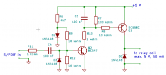
Something like this might work, although you probably have to tweak a component value or two, particularly R9 and R12. The idea is to bias the base of the BC547 at a voltage that is too low to turn on the relay, but with the S/PDIF signal switching, rectification effects in the BC547 should charge the second capacitor (C3), turn on the BC557 and turn on the relay. Use at your own risk, as I've neither simulated nor built it.
The circuit is meant to be connected to a signal tapped off from the S/PDIF line somewhere. The connection from the tap-off point to the circuit has to be kept short, as doing this causes a stub in the S/PDIF line.
The circuit is meant to be connected to a signal tapped off from the S/PDIF line somewhere. The connection from the tap-off point to the circuit has to be kept short, as doing this causes a stub in the S/PDIF line.
Attachments
That's amazing, Marcel. So kind of you! I was just running some simulations of my own.
Even though I don't understand the theory of that (rectification effects in the transistor charging the capacitor), I like your idea to use a 2-stage circuit to supply a steady current for the relay coils.
I was just simulating using a BC 548 on the +5V coming from the COAX to TTL converter, and then using that to trigger a Thyristor in front of the relay. What do you think about that?
- Home
- Source & Line
- Digital Source
- Triggering a relay with S/PDIF?