Not too bad. Replace D3 and D4 with resistors.
Hi ! thanks a lot for your helpful advice. Problem is which value 😱
Do you think that they will improve anything ? i guess the fix the bias current of the output devices ? i would not like to stress them too much ... but i could add those cilindrical heatsinks in case
In this plan, those diodes never turn off, so "speed" is a total non-issue. SPICE would tell you that IF you knew to ask.
Hi and thanks a lot. I have to start with this SPICE asap. Because i would like to sim some very basic circuits. Line preamps is what i am mostly interested in.
For instance i would like to understand better what a major complexity provides to a design like this (i mean the difference between the two schema attached. The second must be completed of course with proper resistors and caps) keeping in mind the main line stage duties ... i.e. to provide very small Vgain (if any) and buffer of the signal to drive a power amp.
This is very important and thank you very much. I was just thinking that.1N914 in a power supply are very likely to BURN UP. Worst-case they do not burn-OUT but instead burn-up a power transformer.
It maybe would help to understand things before randomly "improving".
I would like to identify a diode very good for any low power low voltage application to use everywhere I am interested mostly on dual power supply +/-30V max.
I have abandoned the idea of tube preamps/buffers ... too high voltages and two power supplies ... i am already quite lost with solid state
And i am sure that solid state done right can sound quite nice that i what i am looking for ... a nice sound with some tube qualities ... like space and midrange tone Two things a little missing with this preamp that is clean but also hard and flat I read that it can be a characteristic of the discrete op-amp circuits ?
Last edited:
Any NP0/C0G ceramic cap will do.
Thanks a lot !
you mean like these ?
New Monolithic Ceramic Chip Capacitor MLCC Multi-layer Capacitor 50V 5.08MM IL | eBay
any plastic alternatives ? i often read about the superiority of styrene caps but are quite difficult to find They are used often in phono preamps where precision is very important They look so nice
Attachments
Last edited:
In this plan, those diodes never turn off, so "speed" is a total non-issue. ...
Hi and sorry if i ramble a little more. My thinking is that from my preamp and the one i am attaching (DOA-68) around 40 years have passed.
So my guess is that this design is superior to mine also in parts quality ? ... and i see that it uses 1N914 instead of 1N4001
I wonder why they have decided this ... i do not know at all
They are faster that is clear ... better ? i do not know
If you confirm me that they would be exactly the same i will buy just new 1N4001 of course
Attachments
Why such high power?
Alternative #1 Use these resistors to set the bias current, remove all diodes
Alternative #2 Omit the differential pair
Alternative #3 Switch to single ended topology
Alternative #1 Use these resistors to set the bias current, remove all diodes
Alternative #2 Omit the differential pair
Alternative #3 Switch to single ended topology
Hi ! unfortunately i am not the designer ... cannot answer 😱Why such high power ?
all alternatives sound very intriguing to me expecially if there is something to gainAlternative #1 Use these resistors to set the bias current, remove all diodes
Alternative #2 Omit the differential pair
Alternative #3 Switch to single ended topology
A simpler design similarly great is already a gain in my vocabulary Sometimes less is more
But i really do not know where to start
I was saying that the only thing i am able to do quite easily is to replace some parts
I was very wrong Even just desoldering is proving much more difficult than i thought ... i am using this unit
https://www.amazon.com/YIHUA-Desoldering-Variable-Temperature-Function/dp/B08BK69H2M/ref=sr_1_1?crid=3QO9JQXUWWKPN&dchild=1&keywords=yihua+948+desoldering+station&qid=1607692351&sprefix=yihua+948%2Caps%2C291&sr=8-1
even after a few desoldering it gets clogged up ... a disaster

Do i have to try the copper braid maybe ? it consumes very fast from a video i have just seen.
Last edited:
The only thing you’re going to gain here would be from improved noise or matching in the input pairs. Higher gain, lower noise, that are hand matched may produce improvement. The originals may have been hand matched, and then you’re really into diminishing returns.
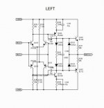
Output stage bias (diode drop related) just isn’t critical, since it is high with respect to the load that it’s driving so it stays in class A in normal use. The voltage across the 68 ohm resistors isn’t critically set to a handful of millivolts. It’s higher. The two back-biased diodes (D101 and 103) are only for protecting the output transistors from being driven beyond the rail. For that purpose, I would have stuck with 4001s, because they can take more fault current. They have absolutely nothing to do with the sound. Their capacitance will only matter well above audio range.
Output stage bias (diode drop related) just isn’t critical, since it is high with respect to the load that it’s driving so it stays in class A in normal use. The voltage across the 68 ohm resistors isn’t critically set to a handful of millivolts. It’s higher. The two back-biased diodes (D101 and 103) are only for protecting the output transistors from being driven beyond the rail. For that purpose, I would have stuck with 4001s, because they can take more fault current. They have absolutely nothing to do with the sound. Their capacitance will only matter well above audio range.
Hi ! thanks a lot for the very helpful advice. I will keep it as it isThe only thing you’re going to gain here would be from improved noise or matching in the input pairs. Higher gain, lower noise, that are hand matched may produce improvement. The originals may have been hand matched, and then you’re really into diminishing returns.
Output stage bias (diode drop related) just isn’t critical, since it is high with respect to the load that it’s driving so it stays in class A in normal use. The voltage across the 68 ohm resistors isn’t critically set to a handful of millivolts. It’s higher. The two back-biased diodes (D101 and 103) are only for protecting the output transistors from being driven beyond the rail. For that purpose, I would have stuck with 4001s, because they can take more fault current. They have absolutely nothing to do with the sound. Their capacitance will only matter well above audio range.
Using the same diodes i have desoldered 😱 and MLCCaps for the 22pF parts.
On another hand my ambitions to try to intervene on old appliances for maintenance / modification have taken a bad rap today The cheap desoldering station I bought is completely blocked after very few desoldering. A disaster and I wonder if I'm the only one who notices. I wonder what maintenance professionals really use considering that some welds use a tin avalanche
At this point the many advices of starting something from the scratch sound very smart to me. What a big delusion indeed. I am very sad.
Thanks a lot again.
.......The two back-biased diodes (D101 and 103) are only for protecting the output transistors from being driven beyond the rail. .....
No. Together with the other two diodes they limit the voltage (and thus current) across the 68 Ohm emitter resistors. Max current roughly 1.2V/68r or 18mA.
You are correct that the actual "type" of diode does not matter at D101 D103.
The D100 D102 diodes (and R101) are selected to bias Q103 Q107 at some "good" emitter current. Actual transistor Vbe and diode Vj will vary from batch to batch. Sometimes 1N4148 (1N914 is an obsolete number subsumed by 1N4148) is a best-fit, sometimes a 1N400x type is a best fit. While random changes may not cause smoke, OP clearly does not know how to know if it is electrically happy.
Also random replacing is going to introduce new bad joints (even the desoldering seems tough). If these three bias parts have a bad joint, both output transistors (or the 68Rs) go up in smoke.
_I_ would figure that Bryston knew what they were doing, much more than me. And rather than being "limited" by the "old" parts of the day, they used their brains. Since nearly all the music I listen to was mastered in those days, on MANY channel systems, I can't care about one very fine line-amp at my end of the chain.
It depends on what you mean by 'like these'. I mean like those (or don't like), but NP0/C0G.you mean like these ?
For such a low capacity (only 22 pF) any type of ceramics possibly will do fine. Even not NP0/C0G type as on your link will do its job.
Last edited:
It depends on your goal. If your goal is to spend time and money - then of cause it is better to search styrene caps. 🙂any plastic alternatives ? i often read about the superiority of styrene caps but are quite difficult to find They are used often in phono preamps where precision is very important They look so nice
You must understand that best depends of the requirements in each specific circuit. For capacitors it highly depends, that is why there are many different types.
A requirement can be: Looking good, though.😛
Or sounding good to golden ears.😛
Tasting good, smelling good, not yet invented, as far as I know.😎
A requirement can be: Looking good, though.😛
Or sounding good to golden ears.😛
Tasting good, smelling good, not yet invented, as far as I know.😎
No. Together with the other two diodes they limit the voltage (and thus current) across the 68 Ohm emitter resistors. Max current roughly 1.2V/68r or 18mA.
You are correct that the actual "type" of diode does not matter at D101 D103.
The D100 D102 diodes (and R101) are selected to bias Q103 Q107 at some "good" emitter current. Actual transistor Vbe and diode Vj will vary from batch to batch. Sometimes 1N4148 (1N914 is an obsolete number subsumed by 1N4148) is a best-fit, sometimes a 1N400x type is a best fit. While random changes may not cause smoke, OP clearly does not know how to know if it is electrically happy.
Hi thanks a lot for the very helpful advice. After my old version the different circuit generations look much more similar than different. I guess they use more modern parts and powerful output transistors. They all use 1N914 at least in the schematic. But as i understand rightly this is not a critical part and the standard 1n4001 were just fine ... i will use the same parts.
this is very true. Unfortunately desoldering with a pump is more difficult than i thought ... i think i have found the reason in a part of the desoldering gun that i will try to replace.Also random replacing is going to introduce new bad joints (even the desoldering seems tough). If these three bias parts have a bad joint, both output transistors (or the 68Rs) go up in smoke.
https://www.diyaudio.com/forums/parts/112606-desolder-gun-pump-3.html#post6445269
often the traces are very thin and delicate. Personally i would like the traces on the pcbs a little thicker than usual. I do not know why they save money on such important part of the devices. The board.
_I_ would figure that Bryston knew what they were doing, much more than me. And rather than being "limited" by the "old" parts of the day, they used their brains. Since nearly all the music I listen to was mastered in those days, on MANY channel systems, I can't care about one very fine line-amp at my end of the chain.
i really like the Bryston phylosophy. They have developed and fine-tuned this gain stage and they have stick with it through the years. From what i read it is a very low THD circuit able to drive all power amps around.
I have found a cap broken anyway ... and two missing on one of the two rails ... in both channel. I would put them in place. I do not think that 2 more 22pF could have a much negative effect. In this way the two rails will be completely simmetrical .. a thing i like.
I am waiting for the parts.
It depends on what you mean by 'like these'. I mean like those (or don't like), but NP0/C0G.
For such a low capacity (only 22 pF) any type of ceramics possibly will do fine. Even not NP0/C0G type as on your link will do its job.
Good to know. Yes i see all 22pF parts and one in the middle 0.1uF But i will leave it The risk of breaking the very thin traces on the pcb is real. 😱
No. Wasting time has no sense. Maybe i am considering line stages more critical than what they really are ? 🙄 For me they are the center of the world. One day i will end with a really great line stage. I see remote control of the volume as a critical point in particular. But also a very handy feature.It depends on your goal. If your goal is to spend time and money - then of cause it is better to search styrene caps. 🙂
You must understand that best depends of the requirements in each specific circuit. For capacitors it highly depends, that is why there are many different types.
A requirement can be: Looking good, though.😛
Or sounding good to golden ears.😛
Tasting good, smelling good, not yet invented, as far as I know.😎
🙂 i have to say that also the look of a circuit is important to me. Some electronic devices are really pieces of engineering art ... for this i do not like very much p2p wiring.
At the audio fairs i used to take pictures of units with a plexiglass top exposing the internal circuitry.
One of my dreams would be a SW that fed with a schematic it puts out a very neat printed circuit.
Then with a precision drill i would drill all the holes myself. And i like a very very thick pcb copper layer. Like half mm. I hate thin layers.
Yet that´s all you do here. Yours and ours.
Hi I'm sincerely sorry for your time. For me it is anything but a waste of time. In the discussion I learned many things and one above the others ... that in a stupid way I tend to minimize both theoretical and practical problems.
I need to address the underlying problems with more humility.
Now I should write to Bryston apologizing for doubting about their design solutions and asking if in the next DOA they can remove a couple of bjts more that bother my sight ... 😱
From my design to the most recent one a pair of bjts is already missing. Good Bryston ! keep on the good job ! less can be more.
But what is simpler and more effective than an output stage made with just a push-pull of darlingtons (i.e. single pair) ? you can always keep the same quartet of input transistors ... with 6 active parts you have a fairytale discrete op-amp.
Am I minimizing the problems again?
Even if you replaced Q103 and 107 with darlingtons you’d still need Q100 and 106, which are not part of the output stage. The only thing the darlingtons would buy is additional load driving capability - like multiple 100 or 200 ohm loads simultaneously. Not needed in a domestic audio system. And those integrated darlingtons don’t work as well as true discretes in these applications, because the internal emitter-base resistors are the wrong values and connected to the wrong place to get a useful class A bias in the “driver”. Better off leaving it as is. If you did build it with discrete drivers/outputs you would need *10* transistors, and probably bias the drivers at 10-20 mA by running a resistor between the bases of the outputs. That would result in an improvement when driving heavy loads - like headphones or multiple daisy chained devices. If you’re not doing that you just don’t need it.
Hi ! do you mean that a PN100 cannot drive directly a PNP darlington like a MJE271 put in the place of the Q100 ? ... just asking.Even if you replaced Q103 and 107 with darlingtons you’d still need Q100 and 106, which are not part of the output stage.
https://www.onsemi.com/pub/Collateral/MJE270-D.PDF
i do not buy a lot the principle of something overkill. I would look always to the noise and THD ... of course if the parts is hugely oversized ... there are problems. Maybe cost for instance ?The only thing the darlingtons would buy is additional load driving capability - like multiple 100 or 200 ohm loads simultaneously. Not needed in a domestic audio system.
The main advantage i see is in the lower parts count mostly
If i am not wrong Q100 and Q103 like Q106 and Q107 form a sziklai pair ?
Looking at some service manual of the late '70s this topology was quite popular .... what is wrong with it ? not enough for a simple line stage ? 🙄 rightly designed and calculated of course
Just 2 bjts ... nice
this is very important and decisive. Thank you. So there is no way that they can be optimally employed in a line stage. And actually i have not seen any line stage using darlington .... and also power amp are very very few.And those integrated darlingtons don’t work as well as true discretes in these applications, because the internal emitter-base resistors are the wrong values and connected to the wrong place to get a useful class A bias in the “driver”. Better off leaving it as is.
If you did build it with discrete drivers/outputs you would need *10* transistors, and probably bias the drivers at 10-20 mA by running a resistor between the bases of the outputs. That would result in an improvement when driving heavy loads - like headphones or multiple daisy chained devices. If you’re not doing that you just don’t need it
Well the Bryston design here uses just 8 😀 Instead my older unit indeed uses 10 bjts My guess is that the newer designs are the better ?
So they have indeed reduced the parts count
This 8 bjts schematic has been kept with minor modifications since mid '80s ? almost 40 years .... so i think that they believe a lot in this design.
If i am not wrong the same gain block is used also for the phono stages ... two in series ? 🙄
Some other discrete op-amps i have seen employ just two bjts at the input instead of 4 ... differential pair ?
I am not saying that 4 bjts could be enough for a very high end discrete op-amp ... but i am not looking for high end performance ... just THD+N of - 90dB more or less ...
- Home
- Design & Build
- Parts
- Would you change anything ?