Well the first thing you need to do is measure what the DC voltage applied to the 24 volt regulators actually is.
Only then will you have an idea how much you can afford to loose with a cap multiplier.
Only then will you have an idea how much you can afford to loose with a cap multiplier.
In fact, it is. A voltage doubler creates lots of extra losses in the transformer and in the capacitors. It's OK to do this for small currents together with a big transformer.As long as the power transformer is properly rated for each circuit, there is no real difference. ....
Well the first thing you need to do is measure what the DC voltage applied to the 24 volt regulators actually is. Only then will you have an idea how much you can afford to loose with a cap multiplier.
Thanks. I will check for sure. I like to isolate the transformer from the circuit also for safety reason. Now i have 230VAC on the board directly 🙁
I wonder if there are special protecting gloves to be used during the measurements.
I am willing to buy them immediately.
In fact, it is. A voltage doubler creates lots of extra losses in the transformer and in the capacitors. It's OK to do this for small currents together with a big transformer.
Hi thank you very much indeed. This is very important. So uch that i have left the idea and revert to a more traditional diode full bridge that appears to me as the common solution around.
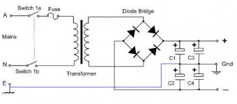
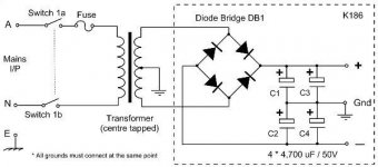
Speaking of split power supplies i see that they can be done with a single output transformer or a center tapped one
I wonder which of the two would be the better approach Its the ground my nightmare ... i do not understand what means a good ground. 😱
I mean there is a safety ground in the wall ... and another ground inside the circuits. Must the audio ground be connected to the ground in the mains ? i am getting mad
Only think i have understood is that the metallic case must be grounded for safety. Because the live wire could come in touch with the metallic case.
Attachments
Last edited:
You don't need gloves, the secondary side is all 100% isolated. Just measure from ground to the input pins of the regulators. Remember the pin outs are different between 78 and 79 types.
You must preserve the original safety features of the original product.
Once you remove the mains transformer the preamp becomes 'a low voltage box'. It in itself does not then need connecting to mains ground for safety (but keep reading 😉) it may (or may not) be beneficial to still connect it to mains ground to improve shielding from hum pickup.
The removed transformer must be used in exactly the same way as the original.
Does the amplifier zero volt line connect to the transformers centre tap and also mains ground ?
If so then you should preserve that in the new box holding the transformer. Assuming that is so then use a metal box that is properly mains grounded and connect the transformer centre tap to this ground. In other words you keep the power supply as it is now.
Only if the transformer is specified as complying with 'double insulation' standards can you think of not mains grounding the power supply. Even then the rest of the construction would have to comply with the relevant safety standards.
So as you seem unsure you should preserve the original electrical configuration and integrity.
Good morning. Yes but also the primary side is on the board. There is a plastic sheet underneath the board protecting the high voltage points.You don't need gloves, the secondary side is all 100% isolated. Just measure from ground to the input pins of the regulators.
For this reason i do not like PCB mounted mains transformers. I would prefer two boards ... one for the psu and another one for preamp circuits connected with a multiwire cable (for DC supply voltages i mean not signals)
https://www.harting.com/sites/default/files/2018-05/IMG_8644.jpg
Remember the pin outs are different between 78 and 79 types.

You must preserve the original safety features of the original product.
Once you remove the mains transformer the preamp becomes 'a low voltage box'. It in itself does not then need connecting to mains ground for safety (but keep reading 😉) it may (or may not) be beneficial to still connect it to mains ground to improve shielding from hum pickup.
The removed transformer must be used in exactly the same way as the original.
Does the amplifier zero volt line connect to the transformers centre tap and also mains ground ?
If so then you should preserve that in the new box holding the transformer. Assuming that is so then use a metal box that is properly mains grounded and connect the transformer centre tap to this ground.
In other words you keep the power supply as it is now.
Only if the transformer is specified as complying with 'double insulation' standards can you think of not mains grounding the power supply. Even then the rest of the construction would have to comply with the relevant safety standards.
So as you seem unsure you should preserve the original electrical configuration and integrity.
Thank you very much for these injections of sanity 😱
I see now much more clearly ... it is much more difficult than i thought 🙁
Giving credit to what i read about its low distortion i just wonder if anything can be done to lower the overall noise instead.
Maybe putting some rubber under the transformer now rigidly bolted to the board ? or use plastic screws ?
I will take out the two big psu caps that hide the other parts ... i hate boards crowded with parts ... there is so much space left unused inside Why stick all things together like this i do not understand ... 🙁
I have to try a desoldering pump i got. 🙄
Last edited:
The primary side might be on the same board but you should have the confidence to work on the secondary side without touching live bits on the primary 🙂
Just measure from the chassis (ground) to pins of regulators. Done in less time than it too read this 😀
Before you can look at 'lowering noise', you need to identify what that noise actually is and where it comes from.
Just measure from the chassis (ground) to pins of regulators. Done in less time than it too read this 😀
Before you can look at 'lowering noise', you need to identify what that noise actually is and where it comes from.
The primary side might be on the same board but you should have the confidence to work on the secondary side without touching live bits on the primary 🙂 Just measure from the chassis (ground) to pins of regulators. Done in less time than it too read this 😀
Thanks again. If i remove the transformer i could be more sure of this and this is what i want to do. I have just to take out two screws and desolder the wires
I will use a 3 wires umbilical going to the board. Very easy to do
Then i could think also to replace the mains transformer but for now the existing can be just fine
Or i can mount the transformer on a rubber mat i already have at hand and leave it where it is.
Very right but i would need an analyzer 🙁Before you can look at 'lowering noise', you need to identify what that noise actually is and where it comes from
Moreover checking the board i have seen a cap truncated ... it could be that that missing cap was the reason of some hiss i was listening.
I will check again when i will have put the preamp together again.
I will report on the result. Now i have to buy parts ... like those 22pF caps 🙄
Thanks a lot again. 🙂
Attachments

Last edited:
The line stage shown should have more than decent power supply rejection (>50-60 dB for sure), and with the power supply even including RC cleanup I very much doubt that it is a problem, assuming the Cs aren't toast of course. (We do seem to be looking at something >30 years old - incidentally, what model is it?) If you can hear hiss, I'd be looking for the cause elsewhere, not in the power supply. Is there any chance of a ground loop being involved?
I did spot a few things in the line stage schematic:
1. Is there any gain before the volume control? The line stage only does 6 dB. Not sure why they were opting for 4k99 + 4k99 to set the gain (R514/513), it looks like it would have a decent amount of oomph and should be able to drive less, like 2k2 each.
2. Series resistor R510 is 4k99. That's too high and would be dominating noise. Try around 1k tops, maybe even half that. Lowpass filtering should be done elsewhere.
3. Look where the ground connection of C1 and C2 goes. If shared with local audio ground, this could inject power supply noise into the ground (if the power supply were noisy, which it shouldn't be). Establishing an extra dedicated power ground return with a decent thick wire (black) running alongside +/-24 V back to the power supply may be worthwhile.
4. It's strange that they have the 49k9 R508 which is just in parallel to the pot. Maybe a previous iteration was using a coupling capacitor in between? Wouldn't have been too bad an idea for sure... I mean, I would expect some input bias current, I can't imagine beta would match between the npns and pnps this perfectly. Maybe 100-200 nA if you're lucky? Measure voltage drop across R510 to know for sure. Is the volume pot scratchy?
Calculated output noise of this circuit comes out to about 3.3 µV idle and 3.9 µV tops even in unmodified form, that's by no means particularly noisy at all. You can still drop idle noise by about 6 dB with the mods outlined in items (2) and (1).
Or i can mount the transformer on a rubber mat i already have at hand and leave it where it is.
If you isolate the transformer with a rubber mat then you might be reducing the safety factor of the unit. There are a lot of 'unknowns' in all this but if the transformer developed a fault then you need to ensure the same protection is in place and that the user would be safe.
If the noise you are experiencing is hiss then I don't really think any of this reworking of the power supply will make any difference tbh. That doesn't sound like a PSU issue to me.
Post #24Hi thank you very much indeed. This is very important. So uch that i have left the idea and revert to a more traditional diode full bridge that appears to me as the common solution around.
Speaking of split power supplies i see that they can be done with a single output transformer or a center tapped one
I wonder which of the two would be the better approach Its the ground my nightmare ... i do not understand what means a good ground. 😱
I mean there is a safety ground in the wall ... and another ground inside the circuits. Must the audio ground be connected to the ground in the mains ? i am getting mad
Only think i have understood is that the metallic case must be grounded for safety. Because the live wire could come in touch with the metallic case.
The left schematic is wrong.
The line stage shown should have more than decent power supply rejection (>50-60 dB for sure), and with the power supply even including RC cleanup I very much doubt that it is a problem, assuming the Cs aren't toast of course. (We do seem to be looking at something >30 years old - incidentally, what model is it?)
Hi ! thanks for the very valuable advice. It is a Bryston 0.5B dated late mid '80s ? the big caps are ROE 4700uF/50V ... i will replace them soon just to be safe
I am really sorry but the schematic i have attached is very similar in concept but it is not the one of my unit ... Bryston have removed it from the archives and i cannot find it again stupid me 🙁🙁🙁
but as i said they are very similar
If you can hear hiss, I'd be looking for the cause elsewhere, not in the power supply.
Is there any chance of a ground loop being involved?
Yes it is a hiss I checked with the preamp with open inputs and connected to the power amp. The power amp alone is quite silent from the speakers ... if i connect the preamp with open inputs i get the hiss ... a more high Hz noise than low Hz noise. 🙁
no after the selector the inputs go to the Volume pot. There was a balance control that i have eradicated and put some wires insteadI did spot a few things in the line stage schematic:
1. Is there any gain before the volume control?
actually Vgain amount is fine Actually i do not need of any gain ... a Volume plus buffer would be fineThe line stage only does 6 dB. Not sure why they were opting for 4k99 + 4k99 to set the gain (R514/513), it looks like it would have a decent amount of oomph and should be able to drive less, like 2k2 each.
Yes ! this is exactly how mine is built ... a 100klog Volume pot and a 3.3uF mkc after it ... unfortunately i do not have the actual schematic. The circuiti is conceptually identical but with a bjts pair more in the middle. The more recent versions have one pair less and more powerful output bjts. If only i had the schematic i could think to mod it similarly to the more recent versions of the circuit. A real pity.2. Series resistor R510 is 4k99. That's too high and would be dominating noise. Try around 1k tops, maybe even half that. Lowpass filtering should be done elsewhere.
3. Look where the ground connection of C1 and C2 goes. If shared with local audio ground, this could inject power supply noise into the ground (if the power supply were noisy, which it shouldn't be). Establishing an extra dedicated power ground return with a decent thick wire (black) running alongside +/-24 V back to the power supply may be worthwhile.
4. It's strange that they have the 49k9 R508 which is just in parallel to the pot. Maybe a previous iteration was using a coupling capacitor in between?
No the pot is fine No noise I have searched a lot for the schematic I am thinking to take a pic of the downside of the board and design the value of the parts on itWouldn't have been too bad an idea for sure... I mean, I would expect some input bias current, I can't imagine beta would match between the npns and pnps this perfectly. Maybe 100-200 nA if you're lucky? Measure voltage drop across R510 to know for sure. Is the volume pot scratchy ?
Wow ... thanks a lot and that is low indeed. My unit is only similar and maybe a little more noisy but for a line preamp this should not be a great issue.Calculated output noise of this circuit comes out to about 3.3 µV idle and 3.9 µV tops even in unmodified form, that's by no means particularly noisy at all. You can still drop idle noise by about 6 dB with the mods outlined in items (2) and (1)
I will take a picture of the downside of the board and draw all the parts on the other side and i will post in
Thanks a lot again for the very kind and helpful support
Good morning ! thanks a lot again. I will check with a tester to see if the bolt fixing the transformer to the board are connected to the ground.If you isolate the transformer with a rubber mat then you might be reducing the safety factor of the unit. There are a lot of 'unknowns' in all this but if the transformer developed a fault then you need to ensure the same protection is in place and that the user would be safe.
At the mains in of the unit the safety earth is connected to the metal frame of the preamp. I checked with a tester and it is at the same potential of the ground on the rca ins and outs but the transformer and the its mounting screws are isolated. So i think the mains transformer is floating ? only the L and N wires enter it and tre wires Vac-0-Vac depart from it and goes again to the board. The rubber mat is only intended for some vibration damping not as an electric isolator ... a transformer often vibrates A mechanical decoupling could be beneficial ?
I see and thanks for that. Yes it is a hiss. When i was removing the caps and diodes i noticed that one 22pF cap was missing in one channel ... there were just the truncated pins (i could have broken it manipulating the unit)If the noise you are experiencing is hiss then I don't really think any of this reworking of the power supply will make any difference tbh. That doesn't sound like a PSU issue to me.
I guess that could be a cause ?
I will proceed resoldering the missing parts and test it again.
This is very important project for me because if i will not get much noise my intention would be to try to build the more modern versions from the scratch
A circuit that can provide a very low noise and THD even with a very basic dual power supply based on off-the-shelf IC regulators must be a really great design indeed.
Now more than the distortion is the psrr parameter that intrigues me. I read some time ago a thread about an amp promising and ultra high psrr. I guess it could almost work without regulation ? that is something Noise is a very bad beast. Sometimes i think that noise is even worse than distortion.
It masks a lot of tiny details .... this preamp will be my training field.
I will replace also the big ones ... they are about 40 years old ... i am doing it now. 🙂
For everyone playing along at home:
Bryston 0.5b schematic - see attached (from the Bryston website - http://old.bryston.com/PDF/Schematics/0.5B_SCHEMATIC.pdf)
User Manual can be found here (pdf)
Bryston 0.5b schematic - see attached (from the Bryston website - http://old.bryston.com/PDF/Schematics/0.5B_SCHEMATIC.pdf)
User Manual can be found here (pdf)
Attachments
For everyone playing along at home:
Bryston 0.5b schematic - see attached (from the Bryston website - http://old.bryston.com/PDF/Schematics/0.5B_SCHEMATIC.pdf)
User Manual can be found here (pdf)
Hi ! thanks. Problem is that the gain blocks are black boxes 😱
I remember the schematic contained in the service manual of a power amp of the same era. I will again for it. Without the schematic is like driving blind ...
- Home
- Amplifiers
- Power Supplies
- Kind request of help to understand a psu circuit