Hi Members,
I would really appreciate your input on a notorious stubborn NAD 3240PE amplifier channel that refuse to work.
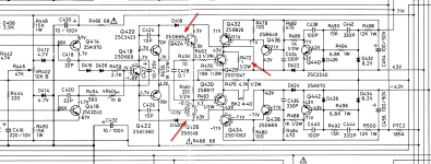
Upon powering-up the transistors on the RH channel Q424 & Q426 as well as BIA resistor R472 burn immediately. This sends 25 VDC on the channel speakers terminals.
These replacement transistors were from ebay so I cannot guarantee they are completely Hitachi originals.
What could cause such misfunction in the right channel circuit.
The LH channel is perfectly fine.
Most of the passive components have tested ok.
I am starting to loose sleep over this and dream about the schematic sometimes.
Please help
I would really appreciate your input on a notorious stubborn NAD 3240PE amplifier channel that refuse to work.
Upon powering-up the transistors on the RH channel Q424 & Q426 as well as BIA resistor R472 burn immediately. This sends 25 VDC on the channel speakers terminals.
These replacement transistors were from ebay so I cannot guarantee they are completely Hitachi originals.
What could cause such misfunction in the right channel circuit.
The LH channel is perfectly fine.
Most of the passive components have tested ok.
I am starting to loose sleep over this and dream about the schematic sometimes.
Please help
Attachments
Welcome
Benvingut
For help will be better if you post in solid state sub-forum https://www.diyaudio.com/forums/solid-state/
Benvingut
For help will be better if you post in solid state sub-forum https://www.diyaudio.com/forums/solid-state/

You must use a dbt (dim bulb tester) to prevent damage and burn ups.
Faults like this always come down to failed output stage components, usually output transistors, drivers and perhaps the pre drivers.
This amp uses a switched rail supply and it is common for the commutation diodes (D422 and D424) to fail although this will not cause the amp to burn up.
If you are fitting replacement transistors then you must begin with the bias setting minimum and I would also recommend you short out the vbe multiplier to force a zero bias condition.
Use the dbt and power up and fault find in the normal way.
(the 1 ohm should only be in circuit for bias setting adjustment, normally it will be linked out)
ebay transistors are likely to be fakes- use modern substitutes
2SD699 = KSC3503
2SB649 = KSA1381
I have used these as substitutes in NAD units with no problem.
AND as Mooly states use a DBT
2SD699 = KSC3503
2SB649 = KSA1381
I have used these as substitutes in NAD units with no problem.
AND as Mooly states use a DBT
Even better is to use a variac to bring up individual sections one at a time. The 3 power supplies can be separately disabled for testing by removing the fuse pairs, and the G-class can be disabled by removing PTC1,2 to provide a low power class AB. Replace each fuse pair initially with a blown fuse with a parallel resistor soldered across it to act as a limiter and current sense. Measure DC input current and voltages around the circuitry (such as Vbe's and rail droppers) as mains voltage is raised in steps. This methods saves further failed parts, and often quickly identifies further failed parts, especially if one channel is ok.
Mine had failed output bjt's and failed PTC's and a blown main cap. Some notes:
Without the high voltage supply, the output stage has no bias, so can only just confirm basic connections with no speaker line voltage.
The main bjts have 3R3 base resistor but no emitter resistor for thermal stability or protection - so I would recommend adding something like 0.33 ohm 3W emitter resistor for each main bjt.
Medium voltage rails don't self-discharge to 0V - so suggest to add something like a 15k resistor across each main cap.
Bias current adjust pots don't connect wiper to un-used end, so suggest you link them. Adjustment on mine was very twitchy, so paralleled with 1k2.
Pots and contacts needed a good contact spray cleaner.
Drivers: 2SA1220/2SC2690 are actually the closest substitute for 2SB649/2SD669.
Also, Unisonic is now making the 2SB649/2SD669! I just bought a bunch from Profusion in the UK: 2SB649AL-T60-T PNP -160V -1.5A | Profusion
Also, Unisonic is now making the 2SB649/2SD669! I just bought a bunch from Profusion in the UK: 2SB649AL-T60-T PNP -160V -1.5A | Profusion
Assuming your transistors aren’t fakes (which they almost certainly are), I’d be checking that R456 isn’t open circuit.
3240PE is a lovely amp. Devilishly complex. There’s so many wonderful ways they can subtly not work.
3240PE is a lovely amp. Devilishly complex. There’s so many wonderful ways they can subtly not work.
Thank you all for your very useful information, I have worked on few of these but this one in particular is very stubborn. Will keep you posted. I have new transistors coming from Analog Metric (spec. match).
Assuming your transistors aren’t fakes (which they almost certainly are), I’d be checking that R456 isn’t open circuit.
3240PE is a lovely amp. Devilishly complex. There’s so many wonderful ways they can subtly not work.
Checked R456 (1K) the red band colour turned brown in comparison, but DV reads close to what is supposed to be.
ebay transistors are likely to be fakes- use modern substitutes
2SD699 = KSC3503
2SB649 = KSA1381
I have used these as substitutes in NAD units with no problem.
AND as Mooly states use a DBT
If I compare the specsheet between these models I see that the IC Max current for the Hitachi is 1.5 A for the KSA is 100 mA ????
as @jvhb states the 1220/2690 are better substitutes, I had used the 3503/1381 and had them in my alternatives list, but will now update that to the 1220/2690.
The BD139/140 combination may also work
The BD139/140 combination may also work
Checked R456 (1K) the red band colour turned brown in comparison, but DV reads close to what is supposed to be.
So it sounds like R456 has gotten hot then? The only way I can see for Q424 & Q426 to both turn on is if the voltage across R456 is too high (hence asking if it was open circuit). If it's been getting hot then the current through it is too high, meaning the voltage across it is also too high, meaning then that the bias on Q424 and Q426 is too high.
So I would suggest your issue is upstream of here. Next look at Q418. if it's open circuit then there is nothing to regulate the bias current and it will go very high. Additionally check VR404, R454 and Q416 for short, and check R452, D436, D416, and Q414 for open.
Also, why nightmare? These sort of diagnostic jobs are really enjoyable, IMO. If you're really not enjoying it, drop the amp in a dumpster and buy another. It's not like they're expensive.
Test on 3240PE
I have run some "live" tests using presumably fake replacement transistors while I wait for the good ones to arrive.
I got hold of a good Variac, connected it and increased the voltage slowly and gradually to avoid burn-up (I went to a max of 20 VAC).
The interesting fact is that on the RH (bad channel) the testing point voltage only went so far. There seems to be a threshold of about 11 VDC where the circuitry could not go beyond. I am sure if I tried to increase the AC voltage there would have been broken parts.
All electrolytics on the RH channel have been pulled and tested individually for ESR value.
The LH, good channel in comparison seems perfectly smooth and in line.
Please comment
Even better is to use a variac to bring up individual sections one at a time. The 3 power supplies can be separately disabled for testing by removing the fuse pairs, and the G-class can be disabled by removing PTC1,2 to provide a low power class AB. Replace each fuse pair initially with a blown fuse with a parallel resistor soldered across it to act as a limiter and current sense. Measure DC input current and voltages around the circuitry (such as Vbe's and rail droppers) as mains voltage is raised in steps. This methods saves further failed parts, and often quickly identifies further failed parts, especially if one channel is ok.
Mine had failed output bjt's and failed PTC's and a blown main cap. Some notes:
Without the high voltage supply, the output stage has no bias, so can only just confirm basic connections with no speaker line voltage.
The main bjts have 3R3 base resistor but no emitter resistor for thermal stability or protection - so I would recommend adding something like 0.33 ohm 3W emitter resistor for each main bjt.
Medium voltage rails don't self-discharge to 0V - so suggest to add something like a 15k resistor across each main cap.
Bias current adjust pots don't connect wiper to un-used end, so suggest you link them. Adjustment on mine was very twitchy, so paralleled with 1k2.
Pots and contacts needed a good contact spray cleaner.
I have run some "live" tests using presumably fake replacement transistors while I wait for the good ones to arrive.
I got hold of a good Variac, connected it and increased the voltage slowly and gradually to avoid burn-up (I went to a max of 20 VAC).
The interesting fact is that on the RH (bad channel) the testing point voltage only went so far. There seems to be a threshold of about 11 VDC where the circuitry could not go beyond. I am sure if I tried to increase the AC voltage there would have been broken parts.
All electrolytics on the RH channel have been pulled and tested individually for ESR value.
The LH, good channel in comparison seems perfectly smooth and in line.
Please comment
Nightmare as in good nightmare, the one where the adrenaline of the challenge keeps you awake thinking. I am not giving-up, this shall go to the end and such amp. will sing again I promise.
So it sounds like R456 has gotten hot then? The only way I can see for Q424 & Q426 to both turn on is if the voltage across R456 is too high (hence asking if it was open circuit). If it's been getting hot then the current through it is too high, meaning the voltage across it is also too high, meaning then that the bias on Q424 and Q426 is too high.
So I would suggest your issue is upstream of here. Next look at Q418. if it's open circuit then there is nothing to regulate the bias current and it will go very high. Additionally check VR404, R454 and Q416 for short, and check R452, D436, D416, and Q414 for open.
Here are latest updates:
Variac slowly raised to max. 50 VAC
1) Voltage across R456=1.8VDC (RH Channel) the bad one.
2) Voltage across R455=2.3VDC (LH Channel) the good one.
3) Voltage on Base of Q424=1.1VDC
4) Voltage on Base of Q426=1.1VDC
5) Voltage on Q418: E=-1.31, C=+1.75, B=-0.67
6) Voltage on Q416 close to specs.
7) Both trimmer are multitrim (20 turns brad new) V404 set at 800 ohm.
8) Voltage on R430=0.5 VDC on both ends.
9) R430 is supposed to be 680 ohm, the one installed by someone else was 18 ohm, it has been replaced.
10) Voltage on R430 is now close to specs.
11) Voltage on both ends of R472 is about 43VDC.
12) Voltage across R427 (BIAS) is near zero & V404 has no effect.
13) There is no DC on speakers terminals.
14) There is no heat or smoke so far.
The mystery continues............
RE: Victory at last
Major breakthrough today:
Further voltage testing showed -0.5 V on the Base of Q418 (it is nearly half what is supposed to be). R430 was the wrong value (18 ohm) it is supposed to be 680 ohm.
Installed by someone else or a mistake on the board.
Re-installing the correct resistor makes the adjustment of the BIAS via V404 possible and everything is working properly. No DC voltage on speakers, BIAS adjusted and signal coming through. Other mistakes I found on the schematic:
1) The four resistors R413, R414, R423, R424 belonging to the soft-clipping circuit are installed as 8.2 Kohm, but if you look at the older schematic they are 6.8 Kohm.
2) On the newer service manual schematic the collector of Q420 is connected directly to the base, which means that it would be impossible to have 1.7 VDC & 70 VDC measured at the same time (across C424). On the older schematic is shown correctly.
It is running a little warm at medium volume.
Many thanks to all members that contribute directly & indirectly especially trobbins & suzyj. 🙂
Attachments
Are you sure about the value of R430 - the emitter degradation resistor for Q407? Q418 is the Vbe multiplier. I have been using the clearer schematic that was available on the internet, which might be the more 'modern' version.
The schematic error around Q420 is obvious from inspection of the other channel.
The schematic error around Q420 is obvious from inspection of the other channel.
All the Emitter degradation resistors are supposed to be 18 ohm (I agree).
It turns out (just discovered it now, another error) that on the schematic there are two R430 resistors, one being on Q407 the other one on the collector of Q404.
The amp is working now, sounds good indeed, but I would say runs a little warm.
Will investigate tonight.
It turns out (just discovered it now, another error) that on the schematic there are two R430 resistors, one being on Q407 the other one on the collector of Q404.
The amp is working now, sounds good indeed, but I would say runs a little warm.
Will investigate tonight.
- Home
- Amplifiers
- Solid State
- NAD3240PE Nightmare