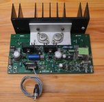
I recently pulled out an heavy amp from our local dumpster and took it home with me. My original intend was to only salvage some parts, since it looked "diy" and felt promisingly heavy.
When I first opened it up, I immediately spotted two pairs of K134/J49s and my interest was sparked right away.
After fixing the PSU I now try to find out as much as possible about this amp, since I got really curios and fascinated.
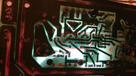
The enclosure and PSU of this amp were obviously diy-ed. Yet the PCB looks fabricated (properly labeled in German language) and soldered by an hobbyist. I therefore suspect that it was some sort of popular diy-kit back in the days, that someone might recognise.
What I found out so far:
* Input Voltages are -54/0/+54 and 80VAC
* Main transistors K134 and J49
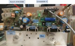
* Further transistors on the PCB: BF469 BF470 BC556B
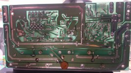
* Only text label on the PCB back says "mos dsm"
My questions would be
* Does anyone recognize the kit/circuit that could leed me to the schematics?
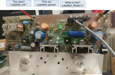
* There are in total more components on the board than I would have expected. Most interestingly an unknown DIP-8 IC and also a big blue component labeled "Modul 1" (please see attached images) that I cannot explain.
* There is a second trimpot (in addition to the bias trimpot) on the board labeled "power". Next to it are two solid pins labeled "HF" ... not sure what those are for.
* All of the above makes me wonder if the board maybe includes some sort of pre-amp stage .... but if so, why is there no volume or tone control?
Any hints will be highly appreciated.
When I first opened it up, I immediately spotted two pairs of K134/J49s and my interest was sparked right away.
After fixing the PSU I now try to find out as much as possible about this amp, since I got really curios and fascinated.
The enclosure and PSU of this amp were obviously diy-ed. Yet the PCB looks fabricated (properly labeled in German language) and soldered by an hobbyist. I therefore suspect that it was some sort of popular diy-kit back in the days, that someone might recognise.
What I found out so far:
* Input Voltages are -54/0/+54 and 80VAC
* Main transistors K134 and J49
* Further transistors on the PCB: BF469 BF470 BC556B
* Only text label on the PCB back says "mos dsm"
My questions would be
* Does anyone recognize the kit/circuit that could leed me to the schematics?
* There are in total more components on the board than I would have expected. Most interestingly an unknown DIP-8 IC and also a big blue component labeled "Modul 1" (please see attached images) that I cannot explain.
* There is a second trimpot (in addition to the bias trimpot) on the board labeled "power". Next to it are two solid pins labeled "HF" ... not sure what those are for.
* All of the above makes me wonder if the board maybe includes some sort of pre-amp stage .... but if so, why is there no volume or tone control?
Any hints will be highly appreciated.
Attachments
Last edited:
I've never seen anything like this one.
The 'Modul' with all its pins could be a thick film module of some sort, perhaps containing the front end differential stages perhaps in an effort to ensure close thermal matching.
The opamp, if it is an opamp, could be a part of the driver circuitry but it is all guesswork.
It doesn't look like it comes from a normal piece of commercial HiFi gear, an instrument or stage amp perhaps.
The pcb reference is "MOS DSM".
Reverse engineer the circuit diagram? (I do that if paid.)
The opamp could be a servo too.
Odd to see a groundlooptrack around the front end.
Reverse engineer the circuit diagram? (I do that if paid.)
The opamp could be a servo too.
Odd to see a groundlooptrack around the front end.
Wow - I wouldn't have thought that I could pose a riddle to the experts of this forum with this one.
In the meanwhile I can confirm that it does ampliy Sound 🙂. I plugged in a sound source and gave it a very brief spin. Also the rca inputs and speaker terminals indicate that it is intended for nf signals.
After spotting the "HF" terminals I was briefly concerned that this might be something completely different.
@MarsBravo
Thanks for the offer, but I wouldn't want to invest seriously into this. I'm just enjoying the puzzle of an entertaining find.
It uses same outputs as Maplin 75watt lateral mosfet amp.
However, looks like quite a different circuit.
Looks like 2 outputs missing ? maybe blown and removed ? or just an option not used ?
However, looks like quite a different circuit.
Looks like 2 outputs missing ? maybe blown and removed ? or just an option not used ?
Hm... My guess would be that the other two outputs are optional. There are no obvious scratches to indicate that anything was mounted. The other channel looks identical.
There are few other optional mounting holes on the pcb and the labels near the fuses suggest that the pcb was
probably meant for different configurations.
There are few other optional mounting holes on the pcb and the labels near the fuses suggest that the pcb was
probably meant for different configurations.
Last night I managed to get the heat sink off one of the ICs. I scratched enough glue off to identify it as an OPA606.
I've also been reading up on the topic of dc servos (as I wasn't familiar with that concept until now - thanks @MarsBravo). After all I've read I think it's very likely that the OPAMP is part of such a dc servo.
Still no hint on the big blue component or the "HF"-pins though.
I've also been reading up on the topic of dc servos (as I wasn't familiar with that concept until now - thanks @MarsBravo). After all I've read I think it's very likely that the OPAMP is part of such a dc servo.
Still no hint on the big blue component or the "HF"-pins though.
My guess is that it is a driver module. It seems (can not see it on the picture) that the module is the amplifying part.
Last edited:
Can you post a sideview picture of the 14 pins blue module?
Any markings?
Notice this amp is capable at the circuit board to support 3 fet's in parallel, on the heat sink two and only one is mounted. NW7557, does that correspond with these Maplins?
Any markings?
Notice this amp is capable at the circuit board to support 3 fet's in parallel, on the heat sink two and only one is mounted. NW7557, does that correspond with these Maplins?
I have several amps based on the original circuit ( Hitachi ) with 2 pairs of transistors.
It is in the development notes.
.
It is in the development notes.
.
I tried to make some better pictures. The blue housing has no markings whatsoever and is made from soft plastic (ABS maybe?).
I will try if the plastic housing can be removed without any damage.
I will try if the plastic housing can be removed without any damage.
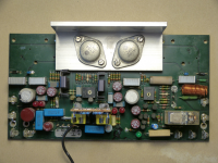
To me this amp looks very similar, though not identical to one that has been quite popular in Germany in the 80's. In this case "Modul1" is essentially a discrete differential amplifier covered with blue resin. Trim pot "power" permits to limit output to something in between 20% to 120%.
Hope this helps - Gerd
Hope this helps - Gerd
Attachments
@Gerd
Thanks a lot. That is indeed the closest match I came across. Do you happen to have a name for the amp/kit so that I can dig deeper?
Maybe you also know what the "HF" pins are for? They're also visible on your picture.
Thanks a lot. That is indeed the closest match I came across. Do you happen to have a name for the amp/kit so that I can dig deeper?
Maybe you also know what the "HF" pins are for? They're also visible on your picture.


Indeed there are similarities on Gerd's amplifier board: more or less the same layout and three fet's in parallel possible. A variation. Is the blue part now the perpendicular board with discrete components?
#14 right picture shows the footprint of the blue part (5-4-5 pins config), suggests a similar encapsulated discrete board.
@ Gerd: Can you post pictures of this small board (comp & copper side)?
It might give us a good insight of the complete design.
The twin-mounted BF's are current mirrors.
A servo with a heat sink is not likely...
Last edited:
I have several amps based on the original circuit (Hitachi) with 2 pairs of transistors.
It is in the development notes.
Further resources are appreciated, if available.
And these 'development notes', too.
This is the MOS amp from ALBS company which was sold in quantities back in the day.
The module is to cover schematic is identical to Elektor Crescendo series. There may be
some sort of protection circuitry in addition.
The module is to cover schematic is identical to Elektor Crescendo series. There may be
some sort of protection circuitry in addition.
The lead regarding "ALBS MOS amp" seems promising. I did a search for that term and came along some images (unfortunately without any further explanation) of amps that also feature that mysterious blue component.
It seems like many variations and version of that amp have been put out over decades. I'll keep digging to see if I can find a closer match.
It seems like many variations and version of that amp have been put out over decades. I'll keep digging to see if I can find a closer match.
Attachments

- Home
- Amplifiers
- Solid State
- Unknown MOSFET Amp K134 J49