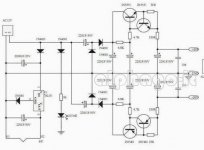
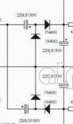
Hi ! i am attaching a power supply that i really would like to understand the working principle (schematic attached)
The input is a single 12VAC ... the output a dual +/-30VDC
How this voltage step-up is possible ? i really do not understand
Are the transistors increasing the voltage ?
Does this kind of psu have a name ?
I really like the fact that starting from a single VAC can provide a dual power supply
Can it have the same performance of a more conventional dual supply using a center tapped transformer ?
Thanks a lot for any help
gino
Attachments
Last edited:
Voltage Multipliers (Doublers, Triplers, Quadruplers, and More) | Diodes and Rectifiers | Electronics Textbook
The transistors do not increase the output voltage, instead they are capacitance multipliers,
which decrease the output ripple.
The transistors do not increase the output voltage, instead they are capacitance multipliers,
which decrease the output ripple.
Last edited:
Voltage Multipliers (Doublers, Triplers, Quadruplers, and More) | Diodes and Rectifiers | Electronics Textbook
The transistors do not increase the output voltage, instead they are capacitance multipliers, which decrease the output ripple.
Hi ! thank you so much for the very kind and helpful explanation
So are the diodes that actually provide the voltage increase ... great
Sorry but i have another one ... is this circuit using a single output mains transformer technically inferior to one using instead the usual center tapped mains transformer ? 🙄
i really like this one ... a lot indeed

I cannot explain why 😱
Last edited:
As long as the power transformer is properly rated for each circuit, there is no real difference.
A half wave rectifier does need larger capacitors than a full wave type for the same ripple voltage.
A half wave rectifier does need larger capacitors than a full wave type for the same ripple voltage.
Last edited:
As long as the power transformer is properly rated for each circuit, there is no real difference. A half wave rectifier does need larger capacitors than a full wave type
Thanks a lot again and perfect ! absolutely not problem in using bigger caps
I just do not quite understand the need of the two caps before the diodes ... dc blocking maybe ? not that is a big issue
Thanks a lot again. Very kind of you 🙂
Thanks a lot again and perfect ! absolutely not problem in using bigger caps
I just do not quite understand the need of the two caps before the diodes ... dc blocking maybe ? not that is a big issue
Thanks a lot again. Very kind of you 🙂
Try and understand and think it through.
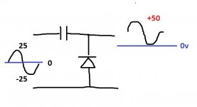
You have single transformer winding, so just two wires. Lets say it has an output voltage of 18 volts measured on a meter. That is an RMS value. We call one of the wires (it can be either one) 0 volts.
If we looked on a scope we would see the voltage on the other wire go up to 25.4 volts as a peak and then down below the zero or centre line to -25.4 volts. This is because the peak voltage is the RMS value multiplied by 1.414 and the peak to peak value is that result multiplied by 2. It is the value of the sine measured from top to bottom.
So the 18 volt transformer produces 25.4v peak and 50.8 volts peak to peak. We will call it 50 for easy reckoning.
You need to understand those figures to understand the doubler.
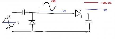
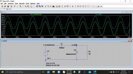
What we do now is connect a capacitor and a diode in series across the transformer. This uses the diode to shift the voltage and reference it to ground. So on the diode our AC voltage is still there but is shifted to be all above the zero volt line. Nothing now goes below 0V. Look at the diagrams to see how that happens.
That is the first part of the doubler. It takes the AC voltage that goes above and below 0V and makes it into the same AC voltage that now starts at 0V and only goes one way above that point. First diagram...
Now we simply rectify that AC voltage with a diode and a cap. Because the AC voltage is now all above zero volts and has a peak value of 50 volts (measured from the 0V line) we now end up with a DC voltage of 50 volts rather than the 25 peak value we started from which would only have given us 25 volts DC. So we have effectively doubled it. Second diagram...
It is all about level shifting. We can triple, quadruple (and even more) an AC voltage using this shifting technique.
Attachments
Try and understand and think it through.
You have single transformer winding, so just two wires. Lets say ....
Hi ! thank you so much for your extremely valuable support. I am printing your words down and i will read them very carefully hoping to understand the principles.
I am very slow at understand even basic things. Usually at school i was lost during the theory lessons ... and i was able to understand something only after the exercises.
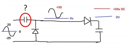
Just one very quick question. Is the cap before the first diode on the left in your schemas really needed ?
its only function is to block any possible DC to me ... diodes function i am beginning to understand but that cap ? what is its purpose ?
However i will putting together some diodes very soon and measure the output
I have already ordered some fast diodes (UF5400)
I love this circuit because it allows to use a single output transformer.
Thanks a lot again.
Attachments
Last edited:
Yes, the cap is essential.
If the cap was not present then the diode would conduct heavily on each half cycle and effectively 'short' the transformer (and the diode would destroy itself).
The cap effectively AC couples the output of the transformer and allows the first diode to level shift the waveform above the zero volt line.
It might be easier to follow with a simulation 🙂
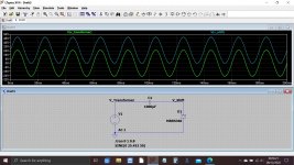
Look at the voltage from the transformer and how it relates to the 0V line.
It goes above and below. The amplitude is 25 volts peak (25 volts in each direction) and the transformer is an 18 volt type. Remember the peak voltage of an AC waveform like this is the RMS multiplied by 1.414
Understand that part first and look at the trace.
Now look what the diode has done. It has level shifted the whole sinewave above zero volts.
The current drawn by the circuit so far is almost zero, just leakage.
Attachments
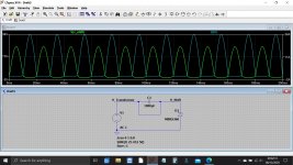
This is what happens without the cap. It is all bad 😀
The diode conducts on the negative half cycle. Can you see how the bottom part of the waveform is shorted out.
The transformer and diode would be smoking now...
Look at the current in the diode on the right hand scale. Not good 😉
The diode conducts on the negative half cycle. Can you see how the bottom part of the waveform is shorted out.
The transformer and diode would be smoking now...
Look at the current in the diode on the right hand scale. Not good 😉
Attachments
Yes, the cap is essential.
If the cap was not present then the diode would conduct heavily on each half cycle and effectively 'short' the transformer (and the diode would destroy itself).
The cap effectively AC couples the output of the transformer and allows the first diode to level shift the waveform above the zero volt line
Hi ! i see ... 24 A ! 😱 ok i will put the caps 😀
caps of any kind and value will do ? 🙄
i mean like also small value plastic caps or unpolarized ones ?
As unpolarized ones can be mounted in any direction, they would be much less critical to me.
I will not have to worry about the mounting.
I have already mounted some polarized caps wrongly ... no explosion because there was like a vent on the cap ... but expensive cap destroyed
Last edited:
Yes 🙂
The current in the diode is only limited by the transformer itself (bigger transformer and more current) and also the wiring resistance.
I added 1 ohm to the transformer in the simulation. If we make that 0.1 ohm then 240 amps flows.
So the transformer and the diode all go up in smoke.
The current in the diode is only limited by the transformer itself (bigger transformer and more current) and also the wiring resistance.
I added 1 ohm to the transformer in the simulation. If we make that 0.1 ohm then 240 amps flows.
So the transformer and the diode all go up in smoke.
The caps are always the problem because these depend on how much current you want to draw from the supply.
So the first thing you must do is actually determine what you want from the supply as it may not be realistically possible to achieve. For powering low current equipment like preamps it is a good solution.
Generally you need big electrolytics that will pass the load current easily.
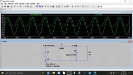
Lets add a load of 50 ohms and use a 100uF cap and then a 1000uF cap. Look at the difference in voltage across the load. The smaller cap is restricting things.
(I'll look in again later 🙂)
So the first thing you must do is actually determine what you want from the supply as it may not be realistically possible to achieve. For powering low current equipment like preamps it is a good solution.
Generally you need big electrolytics that will pass the load current easily.
Lets add a load of 50 ohms and use a 100uF cap and then a 1000uF cap. Look at the difference in voltage across the load. The smaller cap is restricting things.
(I'll look in again later 🙂)
Attachments
Thanks again and perfect. The plots are wonderfully explanatory.
Assuming that i will use a big polarized cap for C1 ... the mounting direction of the initial schematic (portion attached below) must be respected ?
or instead i can mount C1 with the + or - terminal facing the trasformer out indifferently ?
Very likely i will be using polarized caps for C1 as unpolarized one are so difficult to find ... i wonder why Probably no one use them
Attachments
Last edited:
The caps are shown correctly fitted in that diagram.
If you know how much current you need to draw from each rail then we can size the caps appropriately.
What are you going to power with this? and what are the voltages you want?
If you know how much current you need to draw from each rail then we can size the caps appropriately.
What are you going to power with this? and what are the voltages you want?
The caps are shown correctly fitted in that diagram.
If you know how much current you need to draw from each rail then we can size the caps appropriately.
What are you going to power with this? and what are the voltages you want?
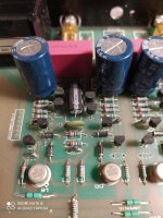
Hi ! thanks a lot again I would like to modify the psu of the preamp attached
I have already eliminated the balance control. I put 4 big Elna blue caps in the preamp channels to give more energy to the channels ... but i have understood that they are too big (1000uF). I have already some Nichicon Gold 330uF that will replace them soon.
Now the mains transformer is soldered on the same pcb and i do not like this
It will be desoldered and placed in a separate case with an AC umbilical going to the preamp
The regulation stage is now done with two 24V IC regulators, + and -
I am sure most people in forum will be horrified by seeing this power supply ? 🙄
Considering the importance of the psu quality ... i do not know what to do 😱
The preamp circuit is a discrete op-amp said to be low in distortion
Problem is that i do not know anything about its psrr vs. freqeuncy ... if it is low a better psu for sure would be beneficial
Now the sound is flat ... bidimensional And the midrange lean
With tubes the sound is more ample ... it fills the listening space more
The very first thing will be to extract the main transformer ... i want it completely detached from the board ... i understand many high end preamps use this solution
I am also willing to replace some parts like caps, resistors, diodes, bjts ... with better parts
P.s. by the way i see now that a little cap is missing on one rail.
Attachments


Last edited:
Unfortunately i saw some time ago the schematic but i cannot find it anymore.
A more updated schematic of the opamp has 2 bjts less ... good 😀
I have already collected some comments about the low parts quality of caps and resistors ... from what i understand discrete op-amps are the corner stone of audio amplification. In a way any amp can be seen as a discrete op-amp ?
A more updated schematic of the opamp has 2 bjts less ... good 😀
I have already collected some comments about the low parts quality of caps and resistors ... from what i understand discrete op-amps are the corner stone of audio amplification. In a way any amp can be seen as a discrete op-amp ?
The power supply I see in the preamp looks to be conventional dual rail with normal transformer with two windings. It looks quite nicely constructed tbh.
So where does the doubler circuit come into all this? If you retain the same transformer then you just have three wires coming into the preamp.
So where does the doubler circuit come into all this? If you retain the same transformer then you just have three wires coming into the preamp.
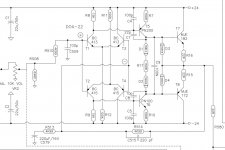
Hi, i am thinking to proceed with some upgrades
preamp circuit
from what i read the preamp circuit has low distortion (good). So the upgrade could foresee only the replacement of some parts with better ones.
As a reference i am attaching the schematic of an updated version of the circuit using, i guess, better parts.
I could replace the diodes and caps accordingly.
I would like to use film caps instead the ceramic ones and the original 1n4001 with 1N914 (they cost nothing)
But also film caps should be quite better than the ceramic ones I hate ceramic caps I prefer styrene ones. Or at least MKP.
power supply
I do not have info about the psrr of the preamp circuit. If it is low, as i think, a better (less noise) power supply could provide some nice improvement.
The transformer will be put outside this is decided. And in case it could be also replaced. I see in the power supply upgrade a way to improve the sound.
After discovering the cap multiplier i was thinking to add an extra stage of filtering with a cap multiplier upstream the existent IC regulators in the space left by the transformer.
If the original has not the right voltage i could buy a new R-core one
If i can lower the overal noise that would be a great thing.
Now the transformer is mechanical coupled to the board. I was even thinking to cut the board with a dremel to separate physically the psu from the preamp circuits and put a 3 wires bridge carrying the +/-24VDC and ground between the two sections ... i wonder why they have not done that in the first place.
Attachments
Last edited:
- Home
- Amplifiers
- Power Supplies
- Kind request of help to understand a psu circuit