Recently I ran across the schematic for the QSC RMX-850A. This is a factory-built present-day amplifier for which the manufacturer publishes a schematic! (Thanks QSC; please never change!)
It's a really cool architecture in that the power rails swing along with the output rail -- go check it out. The only discrete transistors are drivers and outputs, the whole frontend is an op amp. There's no large capacitor in the negative feedback loop, so it shouldn't thump at power on, so we don't need an output relay for civilized behavior.
There's not much to go wrong, and not much to rebuild if it does.
How accurate could an amp with an opamp frontend be? Could we reduce distortion to the single-digit parts-per-million range like the best discrete amps, with a low parts count like the QSC and with no output relay?
Op amps present two challenges:
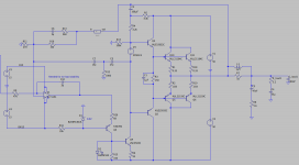
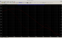
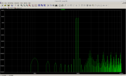
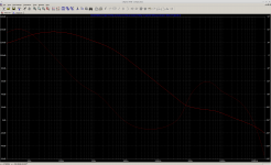
Here's a rough draft of such a circuit. Its distortion floor is about -106db into 4 ohms at worst. Gain and phase margins are healthy, whether measuring at the OPS output or at the op amp's output. I'm not sure the bootstrapped VAS current source is great for avoiding power-on or power-off thumps; that might have to be a real CCS in a finished design.
The design uses TPC for 2nd-order loopgain roll-off, it has >70db of feedback in band. It works well (in simulation) with a high speed, unity-gain stable op amp. It doesn't work well with an LT1115 "audio" op amp; maybe that one has complex internal compensation that interacts badly with the external compensation?
Open question: is it possible to reach the same accuracy without a discrete VAS, using only an op amp driving a CFP output stage as the QSC does?
It's a really cool architecture in that the power rails swing along with the output rail -- go check it out. The only discrete transistors are drivers and outputs, the whole frontend is an op amp. There's no large capacitor in the negative feedback loop, so it shouldn't thump at power on, so we don't need an output relay for civilized behavior.
There's not much to go wrong, and not much to rebuild if it does.
How accurate could an amp with an opamp frontend be? Could we reduce distortion to the single-digit parts-per-million range like the best discrete amps, with a low parts count like the QSC and with no output relay?
Op amps present two challenges:
- Internal compensation. You may wish to use a 2nd order compensation (TMC or TPC) but you can't delete the op amp's internal compensation. That can limit 20kHz feedback and thus limit distortion performance.
- Supply and output voltage limitations, typically +/-15V for many op amps.
Here's a rough draft of such a circuit. Its distortion floor is about -106db into 4 ohms at worst. Gain and phase margins are healthy, whether measuring at the OPS output or at the op amp's output. I'm not sure the bootstrapped VAS current source is great for avoiding power-on or power-off thumps; that might have to be a real CCS in a finished design.
The design uses TPC for 2nd-order loopgain roll-off, it has >70db of feedback in band. It works well (in simulation) with a high speed, unity-gain stable op amp. It doesn't work well with an LT1115 "audio" op amp; maybe that one has complex internal compensation that interacts badly with the external compensation?
Open question: is it possible to reach the same accuracy without a discrete VAS, using only an op amp driving a CFP output stage as the QSC does?
Attachments
I doubt it. Not just swing, but current. I thought about it for a low power MOSFET, but never got around to it.
Lots of poles in the schematic. Build it and see how it works.
Lots of poles in the schematic. Build it and see how it works.
The schematic above has a typo. The pull-down ballast resistors should be 0.33 not 0.033. Fixing that improves distortion performance to better than -110db without reducing stability margins. Cool.
I might try to build this. If there were too many LF poles wouldn't the simulator see them? I guess that's a question of whether spice models of op amps are trustworthy.
I might try to build this. If there were too many LF poles wouldn't the simulator see them? I guess that's a question of whether spice models of op amps are trustworthy.
Another option: use a decompensated op amp like the LT1192, stable at gains of 5 or more.
Then add a 15p cap from its negative input to ground. This cap forms a voltage divider with the 3p cap C10 to provide 5x gain at HF. That pushes the distortion performance to a full -120db.
Doubts remain, but if the thing works it'll work really well.
Then add a 15p cap from its negative input to ground. This cap forms a voltage divider with the 3p cap C10 to provide 5x gain at HF. That pushes the distortion performance to a full -120db.
Doubts remain, but if the thing works it'll work really well.
Another option: use a decompensated op amp like the LT1192, stable at gains of 5 or more.
Try even more decompensated opamps.
LM7171, AD8067, LT1222, THS4121.
Opamp + Common base

The opamp doesn't need to be "super", it just needs to be fairly fast. I've been simulating with LT1191 and LT1192 which are about $4 for a single amp.
There are lots of good choices, some inexpensive. It simulates well with:
A final circuit will clip more nicely. The circuit above is a proof of concept -- it would need a few things to finish it, like a bias spreader and base stopper resistors.
There are lots of good choices, some inexpensive. It simulates well with:
- LT1813, which costs $3 for a dual amp.
- ADA4891, which costs only $1.60 at Mouser for a single amp.
- AD8067 that BesPav mentioned. This costs $4 for a single amp.
A final circuit will clip more nicely. The circuit above is a proof of concept -- it would need a few things to finish it, like a bias spreader and base stopper resistors.
Last edited:
The schematic above has a typo. The pull-down ballast resistors should be 0.33 not 0.033. Fixing that improves distortion performance to better than -110db without reducing stability margins. Cool.
I might try to build this. If there were too many LF poles wouldn't the simulator see them? I guess that's a question of whether spice models of op amps are trustworthy.
Hit or miss. I made a mistake in a little circuit where I had no where near enough base current and the model worked fine.
I almost gave up on this. The trouble was, the loopgain probe showed conditional stability when measuring at the op amp's output. If you tune the circuit for a ULGF of 10Mhz, at 500kHz the loop phase would reach -240 degrees. That's not safe, we must fix it.
Adding a series R-C across the base and collector of the VAS transistor can fix this. It also helps recovery from clipping at the positive rail.
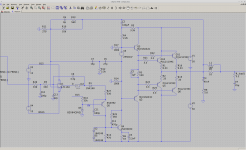
Here's an improved circuit. Clipping looks OK, not the best but not terrible. The distortion floor is around -115db. Phase and gain margins are fine, with or without a load, whether you measure at the op amp output or the OPS output. It's free of conditional stability.
It's not easy to love this circuit. It has seven compensation caps -- C13, C8, C12, C9, C7, C5, and C6 -- each of which alters the loopgain plots. And while it's not totally fragile, it's not the easiest thing to tune either. Hardly seems worth it, just to avoid building a discrete frontend.
Adding a series R-C across the base and collector of the VAS transistor can fix this. It also helps recovery from clipping at the positive rail.
Here's an improved circuit. Clipping looks OK, not the best but not terrible. The distortion floor is around -115db. Phase and gain margins are fine, with or without a load, whether you measure at the op amp output or the OPS output. It's free of conditional stability.
It's not easy to love this circuit. It has seven compensation caps -- C13, C8, C12, C9, C7, C5, and C6 -- each of which alters the loopgain plots. And while it's not totally fragile, it's not the easiest thing to tune either. Hardly seems worth it, just to avoid building a discrete frontend.
Attachments

...Here's an improved circuit. ....
Bias to Q5 should come from BN15 not B15. Q5 Base should be well negative of U1 output which should "probably" be about centered on B15 BN15, not way offset. (I guess it does work, and simple models won't know the difference.)
Biasing the Q5 cascode at +8V limits the current that the opamp can drive through R20 to about 20mA at worst. Lifting the cascode bias point seemed like an easy way to limit the current. Is there a negative consequence of this?
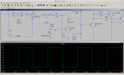
With a couple tiny edits, this thing draws perfect squarewaves. I had to enclose D1 in the loop formed by C11. This ensures the frontend always has HF control over the VAS, or in other words, it ensures that the cascode output is low impedance at HF even if D1 completely switches off (as when clipping or slewing a squarewave.) D1 is only there to prevent the opamp from reverse-biasing the B-E junction of Q5 during clip.
Squarewave and revised cascode attached.
Oh! Since the edits of comment #11 this works with more/slower opamps. Eg. it works fine with an LT1115 now. Fast opamps with light internal compensation produce the lowest distortion, but mid-speed opamps are stable. Really slow opamps still aren't stable...
Attachments
Last edited:
- Home
- Amplifiers
- Solid State
- High fidelity, low parts count