There are several quantitative measurements for low voltage audio power supplies which are easy to implement -- PSRR, Output Impedance (and transient response), Noise, etc. In the digital audio realm, I would guess that reverse PSRR could also be important. More difficult to measure are regulator error amplifier issues.
Which do you consider to be the most important criteria for vacuum tube power supplies?
PSRR, or "Line Rejection"?
Output Impedance (or transient response)
Noise
Which do you consider to be the most important criteria for vacuum tube power supplies?
PSRR, or "Line Rejection"?
Output Impedance (or transient response)
Noise
I think I probably know less on the subject than you, but my only comments are you missed voltage regulation itself as one of the criteria. Also the primary criteria changes according to service: B+ for SE, B+ for PP, screen grid B+, etc.
I think I probably know less on the subject than you, but my only comments are you missed voltage regulation itself as one of the criteria. Also the primary criteria changes according to service: B+ for SE, B+ for PP, screen grid B+, etc.
Yes, that should fall under the tent of impedance and transient response.
Your point is well taken given that we have a lot of heat surrounding these circuits and it might be a good idea to look at the regulation with time and temperature.
And of course,PSRR, or "Line Rejection"?
Output Impedance (or transient response)
Noise
Toughness
Resilience
Survivability to unexpected, even outlandish events
Ruggedness
Tolerance to whatever you throw at it
Reliability and well-behavedness, including under the most difficult circumstances
etc., etc
PSRR and the rest are of limited usefulness if you can benefit from them once or twice until you connect something, like a capacitor, discharged or charged to an odd voltage....
What is "reverse PSRR"? As for what makes for a good supply, the application determines what the requirements are for that. I wouldn't want to specify an excessively fancy one when a lesser one is completely adequate.
It should have stable constant current mode in the range 1..2mA with a 10 turn pot for reforming electrolytics. I allways found that very usefull. Oh wait, we are not talking bench supplies here?
for tube audio projects noise is an important consideration, but for class AB loads you may want to have good transient response. And noise becomes less of an issue because lots of noise can be canceled in the output transformer for Push pull designs.
If we are talking vacuum tube supplies in the narrow definition of series regulator, there is an interesting topology you can try to get massive gain from a single pentode error amplifier, that is to current source load the error amplifier. EF184 is the tube i found ideal for this application.
Last edited:
What is "reverse PSRR"?
Any power supply has impedance on its input and output. For any system, perturbation on the output of one leg can modulate other supplies!
I don't know if it's a problem in the audio domain.
I think you've got this largely covered from a performance perspective, perhaps an oxymoron for a non smps design but I would add efficiency, and an ability to survive severe local EFT events without damage. (I live near the sea and for whatever reason we have a lot of very local lightning strikes like the side of our house, one of our neighbor's house, the power lines, a transformer a few hundred feet away that is connected to our house.
The HV tube and solid state stuff has survived more than one near miss, some of the LV solid state gear needed repair. A few things died over time. Computers all died in short order.
We now have a lot of surge supressors (tripplite and zerosurge).
The HV tube and solid state stuff has survived more than one near miss, some of the LV solid state gear needed repair. A few things died over time. Computers all died in short order.
We now have a lot of surge supressors (tripplite and zerosurge).
Valve amps for speaker output (as compared to valve preamps etc) often have expensive power transformers and output transformers. Couple that with output stage valves that will fail at some time, and rectifier valves if used, then over-current protection management that avoids collateral damage is an important criteria.
In a pursuit of isolating the output stage from the power supply, such that the output stage just sees a substantial capacitor with the correct DCV, then the impedance over and beyond the audio frequency range, as seen looking back in to the power supply, should aim to be as high as practical.
In a pursuit of isolating the output stage from the power supply, such that the output stage just sees a substantial capacitor with the correct DCV, then the impedance over and beyond the audio frequency range, as seen looking back in to the power supply, should aim to be as high as practical.
Why does the output stage need to see a capacitor? I thought it needs to see a stable, low noise, ripple free DC. Sometimes you need a capacitor for stability, but the output stage couldn't care less.
The Zout must be as low as possible to make sure one stage does not modulate the supply of another stage.
Jan
The Zout must be as low as possible to make sure one stage does not modulate the supply of another stage.
Jan
Last edited:
@jackinnj: So far I haven't seen/heard any specific requirements that are different from those for low voltage supplies. What might need extra attention is safety. That might be more important once you go above 100V or so.
Another consideration, which I included in my T-reg, is to shut down the supply after a short current limiting event. Current limiting itself should normally never happen, the supply should be able to provide any requested current in normal operation. A current limit is sort of backstop in unforeseen conditions.
But if it endures for a bit longer than a transient, you can assume that something is wrong and should shut it off.
Jan
Last edited:
I was using a capacitor to represent the simplest single component that can represent a voltage source with negligible ESR and ESL and loop area for signal currents that extend to and exceed the audio range (especially by at least a decade if the amp uses global feedback).
@jackinnj: So far I haven't seen/heard any specific requirements that are different from those for low voltage supplies. What might need extra attention is safety. That might be more important once you go above 100V or so.
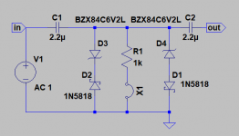
Noise gets tricky. The input blocking capacitors have to be drained down to a few mV -- particularly if a JFET LNA is being used (like Sam Groner's which has Zin of ~100k). So, as with the Tektronix 7A22n plug in, you have to charge/discharge the input capacitor.
Attachments
Tnx Elvee -- I will ask George as he is always blowing things up!
If the supply in question is intended for bench or lab use with unknown loads, there should be considerations for dummies like me who tend to blow stuff up. Adjustable current limiting that responds quickly (no big cap across the output) can prevent the BIG BANG that my HP6448B can deliver. It has 1000 uF internally across its output and goes to 650 volts. It has made capacitors vanish, leaving a big black spot on the PCB and confetti all over the room. It's control loop is slow, taking nearly a second to throttle back it's 60 Hz switcher.
Some sort of OVP or voltage limiting feature would be nice. My old Fluke 407D range switches secondary taps on it's power transformer. This limits dissipation in the pass devices (807 tubes) and limits overvoltage to maybe 150 volts if the control loop goes out (the fine adjust pot went open). The HP will jump to nearly 700 volts if the loop loses control.
Why does the output stage need to see a capacitor? I thought it needs to see a stable, low noise, ripple free DC. Sometimes you need a capacitor for stability, but the output stage couldn't care less. The Zout must be as low as possible to make sure one stage does not modulate the supply of another stage.
Any multi stage device whether it is an audio amp, or a digital computer needs to be fed by a supply with a near zero output impedance over any frequency that could cause unwanted operation of any stage in the device. Any impedance bumps in the power supply can cause unwanted coupling between stages through the power supply. It took me about a year to understand this as a kid trying to make battery powered solid state guitar amps on the lousy carbon zinc batteries of the 1960's. Preamp works, amp works, connect them to the same battery and it motorboats like crazy.
Current limiting itself should normally never happen, the supply should be able to provide any requested current in normal operation. A current limit is sort of backstop in unforeseen conditions.
But if it endures for a bit longer than a transient, you can assume that something is wrong and should shut it off.
Valve amps for speaker output (as compared to valve preamps etc) often have expensive power transformers and output transformers. Couple that with output stage valves that will fail at some time, and rectifier valves if used, then over-current protection management that avoids collateral damage is an important criteria.
In a pursuit of isolating the output stage from the power supply, such that the output stage just sees a substantial capacitor with the correct DCV, then the impedance over and beyond the audio frequency range, as seen looking back in to the power supply, should aim to be as high as practical.
There are three schools of thought here, both with drawbacks.
1) Build a supply with CLC, CRC, or combinations of both. Place a big fat cap across the output where it feeds stages that draw considerable current (output stage). This can work, and is often the preferred choice. However, that big fat cap can do some serious damage to parts like the OPT in the event of a failure. Here the total DCR is kept low and current limiting is usually by a fuse in the primary of the power transformer. A runaway tube can take out the cathode resistor and cap. DO NOT put a fuse in the power transformer secondary unless it is rated for the voltage seen and never use an AC rated fuse on DC. Fuses are nasty when they explode!
2) Build a regulated supply with an active pass element and a control loop incorporating feedback. These are tricky to get right, but can work very well if done right. Many such regulators can go unstable if a large capacitor is connected directly across the output, since the cap upsets the loop response. Such a capacitor is not needed, or wanted if the regulator has a low output impedance across all frequencies that are of interest to the load. Many view these systems a form of "feedback" which IS in the audio path, and therefore to be shunned.
3) Build a CLC or CRC supply and use a capacitance multiplier type of circuit with a zener in the gate / base / grid of the pass device for voltage stabilization. These can be built for current limiting, but overdissipation in the pass device can be in issue. I tend to use these type of circuits for screen grid "regulators" in pentode mode amps. They do not have an ultra low output impedance, but often feed a screen stopper, and with a big fat resistor in the drain lead the output voltage can drop if the output tube is experiencing a larger than normal overload. The right size capacitor at the drain can carry the screen voltage through music transients, but allow the voltage to drop before the screen grid melts if there is a bias failure or other fault.
Thanks George, that was a worthwhile read.
One thing that most lab supplies have, but if your building one: A diode over the output so you can run the supplies in series.
I take it that that HP supply is thyristor controlled in the secondary or triac controlled in the primary? If it is, it likely also has a big inductor and a capacitor bank to get rid of the switching peaks. I guess it has a control loop that senses the differential voltage over the output transistor.
I sometimes borrow a switcher from work made by Delta Elektronika if i need to build something, it has a very fast control loop that goes into current limit within 10mS and it doesnt have excessive output capacitance as well. OVP is also present. Its a 1500W unit that outputs 0-300V and 0-5A. I use this supply at work for working on power inverters in welding equiptment, the constant current mode means that it wont burn any traces if there is a faulty H bridge in the inverter.
Its a rather clean switcher, but still produces some hash on the output due to common mode, not ideal if you want to listen to a setup.
Near the end of the production run of 30W lab power supply modules Delta Elektronika made the E0300-0.1L where the L stands for linear, it features a hockey puck style mosfet as the control element. And i regret getting rid of two of those to this day. I have the schematic somewhere, and a PCB for a Linear 0-300V 0-100mA lab power supply is still on my to do list where the delta serves as a basis.
The T-reg does 0-600V at 400mA max if that would help you out:
T-reg HV regulator | Linear Audio NL
I have PCBs and some of the more esoteric parts.
Jan
T-reg HV regulator | Linear Audio NL
I have PCBs and some of the more esoteric parts.
Jan
One thing that most lab supplies have, but if your building one: A diode over the output so you can run the supplies in series.
I take it that that HP supply is thyristor controlled in the secondary or triac controlled in the primary? If it is, it likely also has a big inductor and a capacitor bank to get rid of the switching peaks. I guess it has a control loop that senses the differential voltage over the output transistor.
I forgot about the diode across the output. It's definitely needed if interconnecting power supplies, and a good idea if playing with anything inductive like an OPT. An arc involving an inductor can generate some big voltages, often of the opposite polarity. It's good to keep them out of the power supply.
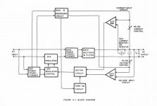
I have never found the manual or schematic for my big HP, but I have found one for it's 500 watt little brother. The block diagram reveals its primitive nature....there is no output transistor. I believe that mine has a triac on the primary instead of an SCR, but I have only had the lid off once. Mine had been left outside in the Florida rain as metal scrap for an unknown time period before it was given to me. It was all rusty on the bottom, but looked clean inside once the dead bugs and stuff was removed, so I plugged it in and it worked, except for the noisy fan which can be heard in my Youtube video where it was used.
75 watt per channel triode mode tube amp prototype - YouTube
I enclosed the block diagram from the smaller unit. Note that Co, the output cap is AFTER the current sensing resistor. It is 500 uF, which at 650 volts can blow stuff in half before the power supply even knows about it. The whole power supply gets pretty noisy under a large load when the transformer is dealing with SCR or Triac chopped up waveforms.
I randomly turned some pots inside to maximize the voltage and current output. I have had it putting out 650 volts at 1.6 amps for long enough to trip the 15 amp bench breaker without issue. Starting it up into a dead short, then removing the short will peg the 700 volt meter. Then it takes several seconds for the charge to be blead off the output caps.
I have a newer 600 volt Sorensen SMPS which should be far more benign, but I haven't finished fixing it yet. It was also very wet at one time in its past.
Attachments
Jackinnj, are you focusing on a power supply to be used inside a valve amp, as is typically done in a single valve amp (eg. a monoblock type amp with a mains AC connection to an external mains)?
Is the aim to deploy a single B+ supply, and use RC or similar distribution to stages within the valve amp, or some other kind of voltage delivery?
Is the aim to deploy a single B+ supply, and use RC or similar distribution to stages within the valve amp, or some other kind of voltage delivery?
- Home
- Amplifiers
- Power Supplies
- What do you consider to be the most important HV supply requirements?