I can't figure out how to get this fixed, I read the other thread on low freq harmonics and maybe it's a problem with how I measure but I have varied measuring but sort get the same also on other amps. Measuring a 5v supply in the same way shows nothing like this.
This is the inbuilt smps +-46 volts measuring directly on one rail using a ADC and 10 to 1 voltage divider and a BP 100v capacitor.

This is a linear 1kw 236,000uF external supply routed to the amp with the inbuilt smps disconnected from the amp and the powergrid. Measured the same way as above.

This is the external linear supply measured directly on the rails but separately i.e disconnected from the amp.

Now suddenly I get a 50hz peak that was not there before and if I disconnect the input on the amp I get the same 50hz peak on the other measurements.
It's a dual mono amp and both channels are the same. If run the rails through 10ohm resistors it's still there but much lower.
Any ideas anyone?
This is the inbuilt smps +-46 volts measuring directly on one rail using a ADC and 10 to 1 voltage divider and a BP 100v capacitor.
This is a linear 1kw 236,000uF external supply routed to the amp with the inbuilt smps disconnected from the amp and the powergrid. Measured the same way as above.
This is the external linear supply measured directly on the rails but separately i.e disconnected from the amp.
Now suddenly I get a 50hz peak that was not there before and if I disconnect the input on the amp I get the same 50hz peak on the other measurements.
It's a dual mono amp and both channels are the same. If run the rails through 10ohm resistors it's still there but much lower.
Any ideas anyone?
50 Hz peak is probably transformer leakage current making its way to ground via the recording input. So much for the easy part. (BTW, what do you mean by "if I disconnect the input on the amp"? - what does it go to, possibly something grounded?)
What sort of recording device are you using?
Can you provide a schematic for your probe / input wiring?
It is certainly possible that your setup works OK as-is... I would have expected more of a difference between supplies though. Possibly what you are seeing is influenced more by capacitor charge current than actual voltage ripple. Which would indicate either a measurement problem or a bad power supply layout.
It does rather sound like you've got an unbalanced measurement setup, that is likely to be problematic.
50 Hz peak is probably transformer leakage current making its way to ground via the recording input. So much for the easy part. (BTW, what do you mean by "if I disconnect the input on the amp"? - what does it go to, possibly something grounded?)
What sort of recording device are you using?
Can you provide a schematic for your probe / input wiring?
It is certainly possible that your setup works OK as-is... I would have expected more of a difference between supplies though. Possibly what you are seeing is influenced more by capacitor charge current than actual voltage ripple. Which would indicate either a measurement problem or a bad power supply layout.
It does rather sound like you've got an unbalanced measurement setup, that is likely to be problematic.
Yes, so the measurement ADC (Creative Sound Blaster X-Fi HD) and the DAC (iFi Audio ZEN DAC) connected to the amp are both on the same computer.
Disconnecting the ZEN DAC from the amp adds the 50hz peak.
The measurement setup is unbalanced (which is what I used is the past without issues like this).
It's a simple voltage divider 10-1/5K-500 ohms and a capacitor on the signal side with another capacitor on ground.
How is the unbalanced measurement setup a problem?
It makes it very hard to avoid a ground loop, and suffice it to say, all bets are off if you've got one of those in there. The way you describe your setup, I can basically guarantee you that you do.How is the unbalanced measurement setup a problem?
Do you have a notebook / laptop with a working battery that you could recruit for some testing, and that the X-Fi HD (+REW) works with? Having the recording side work on battery would provide the required galvanic isolation. If your results persist like that, then they are probably legit. But I suspect you're going to see some changes... (#2 is likely to look more like #3, and you should start to see some differences between #1 and #2.)
If you would like to keep everything on one computer in the long run, you will need a balanced input:
If you would like to add one while spending as little of your hard-earned SEKs as possible, you could get a basic mixer to run into the line-in (e.g. a Behringer Xenyx 1002 - if memory serves, the "2-track" output carries the same signal as the main out, so you'd just need some decent RCA cables). I would recommend a main mix setting of ca. -8 to -10 dB, this usually provides a good match with a 2 Vrms consumer line level input (internal levels: +16 to +18 dBu @ 0 dBFS). Tone controls may need a bit of a tweak for maximally flat (<1 dB) frequency response - some loopback testing would help.
With a somewhat larger budget, I would recommend a USB audio interface; the Focusrite Scarlett 2i2 (now 3rd gen) is a good basic model that would also be an upgrade over the X-Fi HD on the input front (high-frequency distortion performance on the Sound Blaster isn't all that great, though dynamic range is decent; the ADC itself could do better but is held back by the input stage).
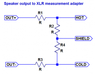
On devices of this league, line-ins are usually mic-ins with series resistors added, forming a voltage divider between those and mic input impedance. They may be usable as-is, but if you don't trust the built-in resistors (they're usually designed to handle about +22 dBu ~= 9 Vrms) you can always make your own attenuator to use with the mic-in. Here's an example for a balanced probe and attenuator that can be used on both single-ended and balanced/BTL outputs:
(R1 = R3, R2 = R4, best hand-matched)
For low division rates, you may be able to leave R2/R4 out altogether, but at higher ones you would get lower noise with them in (even a mediocre input would have the noise equivalent of ~500 ohms tops, good ones <100 ohms, while input impedance is 2-3 kOhms more often than not). I recently suggested something like R1 = 22k || 22k and R2 = 330R for amplifier outputs up to 200 Wpc, if memory serves. Best distortion performance is uaually obtained for mic gain = +20..30 dB, so on a speaker output you can easily shoot for 30-33 dB of attenuation for 100 wpc.
If you are measuring on any device that is entirely floating (like the bare power supply in #3), attach shield to DUT ground somewhere to keep it from floating away. (In a loopback setup the output would usually take care of that already.) Otherwise mains leakage may result in tens of volts of common-mode AC voltage seen at the input, giving input CMRR a hard time.
Attachments
Last edited:
Great info, thanks! It was maybe 10 years ago I did measurements like this and now that you mention it I remember using a laptop which indeed was on battery...D'oh!
I have one now as well so will try again and that Focusrite Scarlett 2i2 looks pretty good and not very expensive, should have gotten that and not the X-Fi-HD.
I have one now as well so will try again and that Focusrite Scarlett 2i2 looks pretty good and not very expensive, should have gotten that and not the X-Fi-HD.
Its certainly much cleaner but I still have the same tendency on both supplies even though the linear supply is a bit better. Its very clean on the speaker terminals, there are no traces of what I get measuring directly on the supply rails below.
Perhaps something else is going on?
SMPS:

Linear supply:

Perhaps something else is going on?
SMPS:
Linear supply:
Ok, how much cleaner 50-500hz can one get it without using batteries?
Interestingly the smps supply has less harmonics starting at 400hz, is that a diod thing or could it be that I am using more film caps in the smps supply.
Interestingly the smps supply has less harmonics starting at 400hz, is that a diod thing or could it be that I am using more film caps in the smps supply.
SMPS is regulated device (with a strong feedback or without) so its low frequency noise depends on it (on a feedback and its regulation).
- with some effort and active and passive filtering applied you may theoretically go as low as batteries or even lover. But it is not an easy way.Ok, how much cleaner 50-500hz can one get it without using batteries?
It is a bit harder with mains powered SMPS because of larger amount of common mode noise.
- with some effort and active and passive filtering applied you may theoretically go as low as batteries or even lover. But it is not an easy way.
It is a bit harder with mains powered SMPS because of larger amount of common mode noise.
I did batteries once and later a massive C-L-C-L-C 10mH 516,000uF dual mono/4 rails which was really nice but not very practical.
I tested adding a 0.33mH/0.29ohm air coil induktor on each rail which brought the 100Hz peak down 6dB but at the cost of bass firmness as you would expect.
I've been using smps with super caps (12 Farads 3V 10x25mm) on 5 and 12 volt supplies for a few years and -yes it takes a lot of resistance and some time to start up up but they are on 24/7 so once up and running they are very stable.
I've been contemplating doing a super cap power amp supply thinking I could more or less decouple (10-20 ohms) the smps and feed a bank of super caps, for my +-45 volt supply it would be 36 pcs which would space wise only be 90x40x25 mm (I would also keep the traditional caps).
That could potentially make for an even better supply and without the fraction of space required for any old style CLCLC...etc power supply.
What's holding me back is the cost for just trying and in combination with not fully understanding how the super caps compare to a smps or traditional supply wrt to ESR. The 3F super caps have a DC ESR of 30 mOhm so each rail would have a 0.54 ESR ohm at DC in my amp....now that I put this is writing I realize it will probably be much better in this respect?, it would then be capable of 83 amps (or 3.7kw) short term. That means I could probably afford a bit of extra L and R between the super caps and the traditional caps in case the super caps are noisy which would also help from a safety perspective.
It would then seem safety is a bigger concern and how small a smps or trafo could one get away with for domestic use?
Any thoughts on this or have anyone tried already?
Great info, thanks! It was maybe 10 years ago I did measurements like this and now that you mention it I remember using a laptop which indeed was on battery...D'oh!
I have one now as well so will try again and that Focusrite Scarlett 2i2 looks pretty good and not very expensive, should have gotten that and not the X-Fi-HD.
I use my 2i2 for rough tests. RIghtmark or TrueRTA. As it is USB powered, it does not inject any harmonics itself. It is actually a darn good DAC.
So, with no input, and levels set to listening positions, can you hear anything from the speakers more than a foot away?
I tried big caps. CLCLC etc. I found CRC to be the most effective. Adding stages did not help much. Like maybe 1 dB. If the last C is big enough, it won't effect your bass dynamics. Once down to the -60 dB or so, wiring topology and physical construction matters as much as the circuit. Pay attention to placement of the bypass caps over on the amp boards.
I tried big caps. CLCLC etc. I found CRC to be the most effective. Adding stages did not help much. Like maybe 1 dB. If the last C is big enough, it won't effect your bass dynamics. Once down to the -60 dB or so, wiring topology and physical construction matters as much as the circuit. Pay attention to placement of the bypass caps over on the amp boards.
A common mode choke might clean it up.
Make sure when talking measurements that there are no noisy electronics running nearby, led's other smps , computers, short cabeling twisted wires, and good grounding.
I run my sound card and jan diddens autoranger from two power banks, no galvanic loops
Make sure when talking measurements that there are no noisy electronics running nearby, led's other smps , computers, short cabeling twisted wires, and good grounding.
I run my sound card and jan diddens autoranger from two power banks, no galvanic loops
Last edited:
So, with no input, and levels set to listening positions, can you hear anything from the speakers more than a foot away?
I tried big caps. CLCLC etc. I found CRC to be the most effective. Adding stages did not help much. Like maybe 1 dB. If the last C is big enough, it won't effect your bass dynamics. Once down to the -60 dB or so, wiring topology and physical construction matters as much as the circuit. Pay attention to placement of the bypass caps over on the amp boards.
No, I don't hear anything 100-400 Hz from a foot away (full volume as it's a power amp). If I put my ear by the woofer I some of it even though its difficult as there are other sounds in the room.
I use my 2i2 for rough tests. RIghtmark or TrueRTA. As it is USB powered, it does not inject any harmonics itself. It is actually a darn good DAC.
Yes, good to know as I ordered one. I have a few bridged amps and plan to build one so need the balanced ADC input.
A common mode choke might clean it up.
Make sure when talking measurements that there are no noisy electronics running nearby, led's other smps , computers, short cabeling twisted wires, and good grounding.
I run my sound card and jan diddens autoranger from two power banks, no galvanic loops
I will try the choke and this is on my workbench with a lot of stuff running close by but I did move it doing a new measurement which gave the same result.
No, I don't hear anything 100-400 Hz from a foot away (full volume as it's a power amp). If I put my ear by the woofer I some of it even though its difficult as there are other sounds in the room.
Just might indicate where "good enough" is. Of course we are greedy and would love see it -120, but not going to happen without a regulator. Just turning on the overhead LED strip light makes my line noise jump 10 dB. If you want to get serious measuring, be sure only incident lights anywhere near you. Transformers need to be in cans, distances managed etc.
- Home
- Amplifiers
- Power Supplies
- Can't get my AMP PS "clean"