Hi,
I bot TPA3255 "dual core" amplifier from AliExpress.
It works but decided to made upgrade.
LC filter inductors replaced to Coilcraft SER2918H-103KL and capacitors to WIMA 0.47uFx250V.
Supply voltage 41V from linear PSU.
After upgrade, switched on. No load.
After ~20sec ceramics capacitors off slave channel PVDD started to explode.
1uFx100V X7R capacitors has been added on PSU plus line and electrolytic as well.
Then 1uF capacitors has been exploded with fire in slave channel when switched on.
Master channel don't explode capacitors at all.
Then twisted wires connected to output terminals, slave channel PVDD ceramics capacitors starting to show fireworks faster.
DC voltage has been tested on TPA3255 inputs before mods. One IC had 3.5V, second 3.9V.
Could get advise that need to do to make slave channel working ?
Attachments

Last edited:
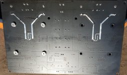
PCB layout
Tested current flowing from PSU using resistor of 5 ohm. Both amps consumed ~120mA. Current consumption unstable (always jumping) and begin to rose. After ~30sec it reach around 250mA and first PVDD capacitor of slave channel blown.
That current instability was seen before changes. Only difference was that current not starting to rose, just beating in 30mA range. I used multimetre having ~1khz bandwidth.
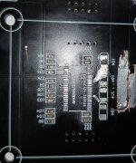
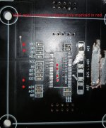
Slave TPA3255 has been removed. There attached PCB view of slave amp. Master amp PCB have VIA's and they depictured in red on slave channel PCB picture.
Master have ground VIA's under TPA3255 and in front. Slave does not have these VIA's. Power ground Pins 26,25 have no direct path to rest of TPA3255 ground pins.
Does this PCB layout could be source of instability of slave amp ?
Tested current flowing from PSU using resistor of 5 ohm. Both amps consumed ~120mA. Current consumption unstable (always jumping) and begin to rose. After ~30sec it reach around 250mA and first PVDD capacitor of slave channel blown.
That current instability was seen before changes. Only difference was that current not starting to rose, just beating in 30mA range. I used multimetre having ~1khz bandwidth.
Slave TPA3255 has been removed. There attached PCB view of slave amp. Master amp PCB have VIA's and they depictured in red on slave channel PCB picture.
Master have ground VIA's under TPA3255 and in front. Slave does not have these VIA's. Power ground Pins 26,25 have no direct path to rest of TPA3255 ground pins.
Does this PCB layout could be source of instability of slave amp ?
Attachments
You can't mindlessly change capacitors. LowESR and MLCC do not match well. restore the original state
I agree with the Dr.
Why did you you want to improve? Seems very complex design. How did it work by itself before the changes and problems?
Why did you you want to improve? Seems very complex design. How did it work by itself before the changes and problems?
Original amp have not good sound for me. That main reason 🙂.
Current consumption been not stable. It beating in some range but not went sharply high. Also DC voltage on TPA3255 signal input pins was significantly different on each chip.
So inductors has been replaced to better quality: CoilCraft SER2918H and output capacitors to WIMA MKS4.
Bay the way capacitors are MLCC near TPA3255 and common bank of standard electrolytic. No Low ESR there.
In addition to what drMordor said:
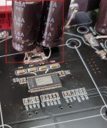
Those SMD caps have too much solder on them (3rd picture).
Chances are you predamaged them doing so and now they sit in a (rigid) bed of solder; not good for long term stability. Those SMD caps easily lose their "end-caps" and then you loose an essential coupling capacitor that could mean more oscillation/damage.
Those electrolyts hanging in the air won´t be doing much good either; every[mm] of wire will add more inductance to your already non-ideal capacitor and can also add to coupling-effects within the layout .
If they are additional caps they might work fine but I wouldn´t do that anyway especially not in a highly sensitive class-d layout.
Better check with a scope if your changes work as intended before you´re sorry.
I´d try the input coupling capacitor for better sound quality.
What are you comparing the amp to sound-quality-wise?
Caps in 3-th picture been removed but that didn't help.
Regarding sound quality this amp give clear metallic addition to voices. Highs was soft enough surprisingly. Noise clearly hereabble too.
I use Class AB amp as reference.
Regarding sound quality this amp give clear metallic addition to voices. Highs was soft enough surprisingly. Noise clearly hereabble too.
I use Class AB amp as reference.
This opamps and input caps, really.this amp give clear metallic addition to voices
D
Deleted member 148505
Hi,
LC filter inductors replaced to Coilcraft SER2918H-103KL and capacitors to WIMA 0.47uFx250V.
Output filter caps for PBTL require 1uF. With no load it will become unstable. Remove WIMA caps and put back blue 1uF caps.
I asked in TI support forum.
There suggested to disconnect LC filter on output and check DC, AC voltage/signals. Such way of testing will works since no significant current will flow through caps.
TI team answer there:
When you are doing the current measurement, have you remove the LC filter? I would recommend you to check OUT pins after removing the LC filter(the caps are not expected to explode without LC filter in my mind... as the current consumption will further decreased without LC filter). It should maintain a 50% duty cycle without any audio input.
As you may noticed on datasheet, section 7.5, with recommended LC filter, the idle current when the device switching at 50% duty cycle are listed out. Without LC filter, it's expected to be ever lower. But according to your measurement, the current consumption is much higher.
I don't think the capacitors are damaged due to over voltage, but more likely due to the high AC current flow.
It's interesting in that ways current really flowing😱.
Started to read that staff: Alternative Paths of the Return Current - In Compliance Magazine
Started to read that staff: Alternative Paths of the Return Current - In Compliance Magazine
These burns like fireworks with sound of exlosion (received from MOUSER) 🙂
12061C105KAT2A AVX Multilayer Ceramic Capacitors MLCC - SMD/SMT 100V 1uF X7R 1206 10%TOL.
After that 2oz PCB trace under cap is melted.
0.1uF 50V originally mounted on board show nice small fire but pcb trace does not melt. I ordered same caps from from local store" samsung 0.1uFx50V x7r. They behave same as originally mounted 0.1uF.
D
Deleted member 148505
Putting bypass ceramic caps directly on the pins of large electrolytics is a no no. It is not an upgrade at all, it will cause oscillation.
Inductors disconected. Added caps shown in picture removed. Tested all pins connections of tpa3255. Then turn on slave chanel pvdd mlcc capacitor near to eletrolytic capacitor bank shows smoke.
How to find that cause excesive current consumption when turn on whithout turning on ?
How to find that cause excesive current consumption when turn on whithout turning on ?
Looks like problem found. Slave TPA3255 RESET pin connected to nothing. 1uF capacitor between RESET and GROUND exist only in far distance from TPA3255.
Master TPA3255 RESET pin connected to DVDD pin through 100K resistor and that IC works OK.
Thanks for advises !
Master TPA3255 RESET pin connected to DVDD pin through 100K resistor and that IC works OK.
Thanks for advises !
Than more think.
Started to check other PCB traces and resistance to ground or even between traces and get in range 0.5Mohm.. till >200Mohm.
In some areas resistance >200Mohm but mostly in range 0.5..10Moh.
PCB material resistance (coper removed) ~0.5mohm for 1mm gap.
Started to check other PCB traces and resistance to ground or even between traces and get in range 0.5Mohm.. till >200Mohm.
In some areas resistance >200Mohm but mostly in range 0.5..10Moh.
PCB material resistance (coper removed) ~0.5mohm for 1mm gap.
- Home
- Amplifiers
- Class D
- TPA3255 dual PBLT. Capacitors blown