Hello,
I have a layout of a stereo Super Gain Clone PCB. I was wondering if some folks here could take a look at the layout and comment. It separates the signal and power ground as per Bob Cordell's schematic in Chapter 27 of Audio Amplifiers.
I have the complete project in a github:
GitHub - profdc9/SuperGainClone: A stereo layout of Bob Cordell's Super Gain Clone amplifier.
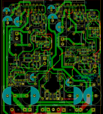
There are two pictures of the layout. One has the ground plane marked, the other does not. The ground plane corresponds to the power "dirty" ground, while the signal ground is wired point-to-point to the various places it is a reference. There are some small breaks in the ground plane to jump tracks. The two channel inputs have separate signal grounds that are joined together by the hum breaker resistors. The channel input grounds should be joined together at the input connectors.
Thanks!
I have a layout of a stereo Super Gain Clone PCB. I was wondering if some folks here could take a look at the layout and comment. It separates the signal and power ground as per Bob Cordell's schematic in Chapter 27 of Audio Amplifiers.
I have the complete project in a github:
GitHub - profdc9/SuperGainClone: A stereo layout of Bob Cordell's Super Gain Clone amplifier.
There are two pictures of the layout. One has the ground plane marked, the other does not. The ground plane corresponds to the power "dirty" ground, while the signal ground is wired point-to-point to the various places it is a reference. There are some small breaks in the ground plane to jump tracks. The two channel inputs have separate signal grounds that are joined together by the hum breaker resistors. The channel input grounds should be joined together at the input connectors.
Thanks!
Attachments

Last edited:
What are you planning to use for the inductor in the Thiele network? It needs to be an air core inductor if you want low distortion.
You won't like this suggestion: I suggest moving the bulk electrolytic caps up to the LM3886es and just have some local decoupling by the power connectors.
I would use pours for the VCC and VEE connections to the LM3886 and remove the two staples between the VCC/VEE in the middle of the board.
I'd also move the feedback connection from pin 3 of the LM3886 to the inductor in the Thiele network. You may as well remove whatever voltage drop across the output trace with feedback if you have the opportunity. 🙂
You have acid traps by R16, D3, and D10. I'd address that.
Don't forget to let the LM3886 overhang by a little so the PCB doesn't rub against the heat sink. What are you doing for mounting? It looks like you may have forgotten the mounting holes.
Can your rectifier diodes handle the ~14 A of current the LM3886es are able to output?
I recommend joining the grounds together at the OUTPUT connectors. You can read more about that here: Taming the LM3886 Chip Amplifier: Grounding – Neurochrome
Hope this helps.
Tom
Last edited:

An air core inductor will be used, it will be stood up on end.
I think it wouldn't be such a great idea to put the bulk electrolytic caps away from the power entry. Large half-wave rectified currents will be flowing through the ground and they will have to be routed separately. This will be superimposed on the output ground causing hum for example. Isn't it best to place the bulk electrolytic caps at the entry to the board so that the charging currents of these are kept off any other ground? The CMRR of the LM3886 (110 dB typical) should be able to handle the small voltage drop across the VCC/VEE of any of the highly smoothed transients between the bulk and local decoupling capacitors.
I do not understand why to tie the output grounds together. Wouldn't this cause cross-channel coupling because they are sharing the same voltage drop path to ground and the output can be a high current so this voltage drop could be significant?
Do you use a hum breaker resistor between signal ground and power ground? I have used them to try to remove ground loops which can be a significant cross-channel noise source that could possibly swamp any small, probably imperceptible effects from distortion. The inputs are bonded together so that any voltage drop between their grounds occurs at the hum breaker resistors which breaks the ground loop formed between the amplifier and preamplifier through the mains.
Could taking the output from the output trace rather than the output pin do more harm than good? The LM3886 has decent loop bandwidth and if it oscillates that is bad news, so I would tend to keep the feedback loop area as tight as possible. Yes the output trace produces some loss but generally there will be at least a meter or two of speaker cable (as well as the output network) which probably has a much bigger effect than the small trace.
I fixed the acid traps but they don't seem to be a problem in modern PCB manufacturing. I fixed the overhang of the LM3886 and added mounting holes.
What are you planning to use for the inductor in the Thiele network? It needs to be an air core inductor if you want low distortion.
You won't like this suggestion: I suggest moving the bulk electrolytic caps up to the LM3886es and just have some local decoupling by the power connectors.
I would use pours for the VCC and VEE connections to the LM3886 and remove the two staples between the VCC/VEE in the middle of the board.
I'd also move the feedback connection from pin 3 of the LM3886 to the inductor in the Thiele network. You may as well remove whatever voltage drop across the output trace with feedback if you have the opportunity. 🙂
You have acid traps by R16, D3, and D10. I'd address that.
Don't forget to let the LM3886 overhang by a little so the PCB doesn't rub against the heat sink. What are you doing for mounting? It looks like you may have forgotten the mounting holes.
Can your rectifier diodes handle the ~14 A of current the LM3886es are able to output?
I recommend joining the grounds together at the OUTPUT connectors. You can read more about that here: Taming the LM3886 Chip Amplifier: Grounding – Neurochrome
Hope this helps.
Tom
I initially missed that you had the rectifier diodes onboard as well. So you're right. Moving the bulk electrolytic caps would blow performance as you'd get rectified pulses of current flowing through a large section of the board.
If you join the signal ground and the power ground at the output connector, you get a lower error voltage developed at the output of the amp. You can read my analysis here: Taming the LM3886 Chip Amplifier: Grounding – Neurochrome
And, no. I don't use a resistor between ground nets. I can get better performance by managing the grounds properly on the board.
I agree that acid traps aren't huge issues these days, but I still see no point in creating them when they're easily avoided.
Tom
Last edited: