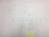
I am designing a 300b all dc coupled tube single ended amp and would like to ask your comment on my circuit. Initially I am thinking about using TL783 to fix the current of each tube so as to maintain a stable anode output voltage to the next stage. But I later think that it should be possible to use cathode bias tech to let them maintain their anode output voltage.
Enlightened by the comment noted in DIYAUDIO I come up with this separate power rail idea for different stages in order to have the cathode bias be lower to the value which should be able to compensate the change in grid voltage. The circuit now has only 2 power rails and if this idea is feasible I should try to make the 6sn7 and 6dj8 be on separate rail too. And I guess the 2 secondary cores should completely be separated for this to work (i.e. not one core with different voltages tap). Thanks for your comment in advance.
Enlightened by the comment noted in DIYAUDIO I come up with this separate power rail idea for different stages in order to have the cathode bias be lower to the value which should be able to compensate the change in grid voltage. The circuit now has only 2 power rails and if this idea is feasible I should try to make the 6sn7 and 6dj8 be on separate rail too. And I guess the 2 secondary cores should completely be separated for this to work (i.e. not one core with different voltages tap). Thanks for your comment in advance.
Attachments
Last edited:
I've built a few power amps with stacked supplies. I would leave out the cathode resistor and bypass cap of the 300B. It's unnecassary and some my claim that not having the elco in the signal loop "sounds better".
When using regulators make sure to regulate 300B and 6SN7 supplies. Or leave the regulator out on both. The bias of the 300B swings with the B+ supply of the 6SN7 and when both swing with line voltage changes it evens out.
You could incorporate safety diodes so the 300B grid doesn't turn positive during switch on.
Your 1k27 cathode resistor at 85mA will get a bit hot, I imagine. (The schematic appears to have 232v and earth running down the middle.)
kind regards
Marek
kind regards
Marek
Last edited:
Nice to see you took a long time puzzling with this.
It's hard to graps this puzzle in an instant, but a few things stand out:
While I assume this works on paper, I do think you won't be able to get rid of hum.
The input tube has it's volume control referenced to it's anode, am I right? No matter how good you'll be able to get that power supply ripple under control, every ripple there is amplified in full by the amp, at least 4 times by the 300, and another 500 times or so by the 2 tubes before, all in all around more than a thousand times. There's no way you get this hum free.
Another thing is the 300b's power supply. Besides being an absolute waste of power, I wouldn't recommend putting that high voltage on it.
One of the strong points of fixed bias is that one doesn't need cathode resistors (or at least much smaller ones).
So I'd redesign the volume control as well as the power supply for the 300b.
I think the centre line of the schematic misleads. If you rub out the left hand earth symbol and put a break in that line (at "231v") between the input capacitor (at earth) and the 232v mark in the middle, it is now just a stacked power supply and so with a rejigged resistor or two, can omit the wasteful cathode resistor in the 300b cathode. The bottom line is earthed presumably.
If not that, then you are telling us the bottom line is at -231v and the centre line is at earth.
kind regards
Marek
If not that, then you are telling us the bottom line is at -231v and the centre line is at earth.
kind regards
Marek
Last edited:
Thanks for your comment.
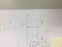
The input is put on that way as I guess the ground point is better set at the existing point for safety (lower top voltage from either side with reference to ground). Your point let me rethink the input ground position. I think hum will be there only if hum exist in the picture below. Is that right?
The 300B B+ voltage should also be lowered and the quiescent voltage will not be affected in fact by the lower B+. The cathode bias is deliberately set on ~1.3K. I calculated this value from the slope of loadline and I think this bias resistor can maintain the 300B to work at the same quiescent voltage from a wide range of grid voltage (if the grid voltage lower, the bias point will compensate to about the same value, vice versa). Fixed bias cannot achieve that but I don't know if this compensating effect worth the extra power consumption. Each cathode bias resistor will consume around 10W. The B+, if need to accomodate this cathode resistor, should be not less than 85mAx1.27k+410V = 520V .
Attachments
Last edited:
I think the centre line of the schematic misleads. If you rub out the left hand earth symbol and put a break in that line (at "231v") between the input capacitor (at earth) and the 232v mark in the middle, it is now just a stacked power supply and so with a rejigged resistor or two, can omit the wasteful cathode resistor in the 300b cathode. The bottom line is earthed presumably.
If not that, then you are telling us the bottom line is at -231v and the centre line is at earth.
kind regards
Marek
The centre is set to ground to higher safety (lower voltage different from both side).
Hum is always going to be there because the input tube has it's reference between cathode and grid, the ground, as you set it is, even though there's lots of rc- time/power supply filtering there, referenced to a power supply. The rejection ratio of the power supply is basically 0, or even positive.
[QUOTE7] The rejection ratio of the power supply is basically 0... [/QUOTE]
Which power supply?
.... the 300B C-L-C PSU (using in tons of amps), or the driver C-L-C -R-C (R-C) PSU. 😛
Which power supply?
.... the 300B C-L-C PSU (using in tons of amps), or the driver C-L-C -R-C (R-C) PSU. 😛
It really doesn't matter. In this case it's the 6dj8 supply.
Never use a volume control referenced to the anode power supply.
Never use a volume control referenced to the anode power supply.
I've built a few power amps with stacked supplies. I would leave out the cathode resistor and bypass cap of the 300B. It's unnecassary and some my claim that not having the elco in the signal loop "sounds better".
The 300B cathode bypass cap is not option and sound quality will absolutely not improve if you remove it. These negative effects are increased with direct coupling and the higher resistance between filament and ground.
In a stacked supply amp the cathode resistor is an option and if that R goes, then so can the bypass C. I never wrote to just remove the C.
Ah, yes, you're quite right that there's no need for the bias resistor if the driver's negative plate voltage is sufficient. I wonder why the builder has them both?
I've built a few power amps with stacked supplies. I would leave out the cathode resistor and bypass cap of the 300B. It's unnecassary and some my claim that not having the elco in the signal loop "sounds better".
When using regulators make sure to regulate 300B and 6SN7 supplies. Or leave the regulator out on both. The bias of the 300B swings with the B+ supply of the 6SN7 and when both swing with line voltage changes it evens out.
You could incorporate safety diodes so the 300B grid doesn't turn positive during switch on.
I agree about the cathode resistor of the 300b wholeheartedly, but it does help against overload of the 300b when the amp is switched on.
You can delay the filament supply and/or the voltage supply of the 300b, to be switched on after the 6sn7 is fully working. Otherwise one has no negative grid voltage when switched on. Direct heated tubes conduct within a second or two. The indirect ones take 10 seconds easily.
One more thing:
What's the T-section (ground wire and 2 resistors, gnd labeled "232 volts") doing exactly?
This might be problematic as it is a series resistor that couples the input voltage (and current) of the 300b driven by the 6sn7 driver stage.
I can imagine all sorts of things (rf, motor boating, hum, feedback loops etc) happening there.
Also: anybody have an idea how to fix it when there's 2 channels that use the same power supply, or is it just a case of connecting the 300b gnd to the anode supply of the driver stage?
It's just a case of connecting the 300B ground to the anode supply of the driver stage. The voltage drop across the driver stages anode resistor sets bias of the 300B.
Ah, yes, you're quite right that there's no need for the bias resistor if the driver's negative plate voltage is sufficient. I wonder why the builder has them both?
It is because I worry the grid voltage , which is in fact from the anode of the previous stage, will gradually drift as time goes on.
I think I really need to put back the ground point to the cathode side of preamp tubes and let the input also be ground to that side. The signal to be amplified is the AC with reference to the cathode and so input ground to anode will in fact let the grid to see the full ripple as against the cathode and amplify the ripple noise.
Why not just clone or adapt already successful 3 stage DC amplifier?, like Komoro for stacked supply, or Morrison for split rail solutions.. no need to re-invent the wheel?
- Home
- Amplifiers
- Tubes / Valves
- All dc coupled 300b se design