I have an Electrocompaniet AW100 power amplifier I got for free, as it didn't work. Turns out, several transistors in the left channel has blown, causing a short circuit.
I managed to find close matches (but not quite). Replacement will be as follows:
2SC2824 --> KSC2690AYS
2SA1184 --> KSA1220AYS
2SC2681 --> FJA4310OTU
2SA1141 --> FJAF4210OTU
They do have some differences, especially max heat dissipation and bandwidth, but I figured 30Mhz would do fine here, even though the originals are 90Mhz (please correct me if that isn't true!).
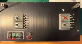
I've attached an image with the broken transistors marked. I assume they complement each other, so I have enough parts to replace all of them.
However, here comes a list of questions I've found difficult to figure out:
1) Should I replace transistors on the other channel as well, so they're equal?
2) What type of adjustment should I do, and how do I do it? There are two pots on the board, and the service manual talks about adjusting the idle current (the service manual is for newer models, so not sure if it's correct in my case - the schematic only fits roughly).
3) Are there any other pitfalls I should be aware of?
I managed to find close matches (but not quite). Replacement will be as follows:
2SC2824 --> KSC2690AYS
2SA1184 --> KSA1220AYS
2SC2681 --> FJA4310OTU
2SA1141 --> FJAF4210OTU
They do have some differences, especially max heat dissipation and bandwidth, but I figured 30Mhz would do fine here, even though the originals are 90Mhz (please correct me if that isn't true!).
I've attached an image with the broken transistors marked. I assume they complement each other, so I have enough parts to replace all of them.
However, here comes a list of questions I've found difficult to figure out:
1) Should I replace transistors on the other channel as well, so they're equal?
2) What type of adjustment should I do, and how do I do it? There are two pots on the board, and the service manual talks about adjusting the idle current (the service manual is for newer models, so not sure if it's correct in my case - the schematic only fits roughly).
3) Are there any other pitfalls I should be aware of?
Attachments
I wouldn't even think of touching the good channel until you have repaired the faulty one.
It would help to see a circuit but the two common adjustments are for quiescent current (bias current) and DC offset voltage. Without a manual we don't know what the current should be although you could always compare to the good channel as a rough guide.
DC offset is always set for zero volts at the speaker terminals. (assuming it is a dual rail supply amp. A single rail amp would have a midpoint voltage adjustment instead).
We always recommend the use of a DBT (dim bulb tester) when fault-finding, however if this is a high bias or Class A amp then that might be problematic initially, and you may have to see in that case if the bias current can be reduced for testing.
It has at least two voltage rails, so I assume the offset should be 0 volts then, measured at the speaker terminals.
1) Where would I measure the bias current? Will there typically be a simple way to do it without having to break the circuit?
2) Just to be sure.. if I feed the amp with a signal and measure it with a scope on the speaker terminals, with no speakers attached, do I risk destroying anything?
3) I have a DBT in the making, however I can't get old fashioned bulbs. I have halogen, though, will they work?
4) If using a DBT with a high bias amp, what would the consequences be? Do I risk wrecking anyting?
Thank you! 🙂
Bias current is often deduced (calculated) from measuring voltage across a low value resistor within the circuit... typically an 'emitter resistor' on one of the output transistors.
Solid state amps are fine to run with no load.
Halogens should work OK, the filament has similar characteristics to normal GLS type bulbs.
A high bias amp (such as Class A) draws a high current as normal and that may mean the bulb lights and seems to show a problem when none exists.
Solid state amps are fine to run with no load.
Halogens should work OK, the filament has similar characteristics to normal GLS type bulbs.
A high bias amp (such as Class A) draws a high current as normal and that may mean the bulb lights and seems to show a problem when none exists.
Circuit for AW-100
https://www.google.com/url?sa=t&rct=j&q=&esrc=s&source=web&cd=&ved=2ahUKEwjQm9SEp7fsAhV0mVwKHSA6Bd0QFjAKegQIARAC&url=http%3A%2F%2Fwww.amplimos.it%2Fimages%2Felectrocompaniet-aw-100-power-amplifier-schematic.pdf&usg=AOvVaw2NOS3aCsXL2C80MJEfGJt5
or
Free Electrocompaniet Diagrams, Schematics, Service Manuals :: Schematics Unlimited
@Mooly thanks a lot!
@Ferret I have the same schematics, unfortunately they are of a much later revision (about 9+ years). No op-amps in my box 🙁
@Ferret I have the same schematics, unfortunately they are of a much later revision (about 9+ years). No op-amps in my box 🙁
Its easy to rush in and change outputs because they have blown.
But why have they blown ?
Its always worthwhile checking driver circuit for bad components too. Sometimes a blown output can blow its driver too.
Nothing worse than replacing numerous transistors at cost only to find they blow again on first power up.
A trick I sometimes use is to leave outputs out of circuit and feedback VAS output into LTP return. The circuit can then power up and you can check for DC on output and bias voltage.
Its easy to rush in and change outputs because they have blown.
But why have they blown ?
Its always worthwhile checking driver circuit for bad components too. Sometimes a blown output can blow its driver too.
Nothing worse than replacing numerous transistors at cost only to find they blow again on first power up.
A trick I sometimes use is to leave outputs out of circuit and feedback VAS output into LTP return. The circuit can then power up and you can check for DC on output and bias voltage.
Not sure what VAS or LTP is.. as for the reason why it blew, I'm not sure. A big 10mF capacitor was leaking badly on the affected side, and of the power transistors, only one pnp seemed bad, even though they are pairs in parallel. I've got my current limiter set up, though, so hopefully I can avoid another bang (I hope?).
The circuitry of this amp seems rather simple, so if I knew what to look for I don't think it would be too difficult to decipher the circuit. I'm not very knowledgeable, however, as I probably demonstrate 🙂
Another question: since this amp has both a negative and a positive supply, how would I best measure the speaker terminals with a scope? I assume connecting the ground clip to the negative side is a no-no?
The amps neg speaker out is grounded so scope ground to there. As nigel said there might be problems pre output that caused the fault. Try the bulb test before you put the new transistor in too see if anything else is shorted, but if you can use a low power bulb ( they limit the current more, I=P/V, so a 12watt bulb limits to .1 amp a 120w 1 amp.) Then compare the voltages with the good side.
A big 10mF capacitor was leaking badly on the affected side
Might want to check the bridge rectifiers are okay (D1 and D2) - make sure there are no shorted diodes.
- Home
- Amplifiers
- Solid State
- Replacing transistors in a power amplifier