Hi guys,
Just wanted to clarify some doubts I had with biasing issues on SS amplifiers. I am really interested on working on amplifiers and anything related to audio. I have been reading on amplifiers.
So here is the series of events on the project I am working on:
As per what I have read online regarding what could blow the output stage (some reasons):
I would like to clarify about the biasing circuit used on this amp. I have done some research on Vbe multiplier circuits but most of the circuits I came across the variable resistor is connected to the base of the Vbe multiplier. However in this unit the VR is connected to another transistor’s base Q6010. I am finding it a bit hard to grasp how this works. Could someone kindly explain.
Q6010 is placed next to one of the drive transistor and it has got what looks like thermal compound applied to it. What is the reason for this?
If it was a biasing issue and some how it caused the output transistors to short out, note B-C-E were shorted - why didn’t it take out the drive transistors? The drive transistors still checks out ok.
All of the components related to the biasing part of the channel checks out ok but hypothetically speaking what component failure for e.g.: the potentiometer’s contacts loosing connection, some kind of thermal effect messing up with the biasing circuitry’s transistors?.
If its some kind of an issue which only causes the fault when power is applied what further troubleshooting should I be doing on this circuit? At the moment I am waiting for the replacement parts to arrive but meanwhile I would like to figure out what exactly caused the fault - could I power up the amp without the output transistors and see if the proper voltages are preset which is shown on the SM and lets say if the drive transistors are faulty, ‘leaky’ for instance would I be able to measure that?
Based on what I have detailed above, what’s your opinion for the reason for the fault to occur?
Thanks in advance for the help.
P.S - I couldn’t find replacement for some of the transistors and resistor so here are the equivalents that I have ordered
2SC1740S-S ——— 2SC2240
2SA1930 ——— A1837
0.22 Ohm 2W emitter resistors —— 0.22 Ohm 5W
Also note that there are some film capacitors which looks a bit black, I am not sure it was like it to start with. It measures ok especially when compared to a working circuit. Hope you can see it in the photo.
Just wanted to clarify some doubts I had with biasing issues on SS amplifiers. I am really interested on working on amplifiers and anything related to audio. I have been reading on amplifiers.
So here is the series of events on the project I am working on:
- Output transistor Q6050 was shorted and one half of the emitter resistor R6100 was open (left channel) and the B+ fuses were open.
- So I borrowed the two output transistors and the emitter resistor from a working channel which was not used. Replaced the fuses however I didn’t replace the driver transistors(I should have!).
- Powered on the unit and measured the biasing voltage at the test points and it was within specs given on the SM. However I should add that I didn’t monitor it long enough.
- Played some signal through it and it was working perfectly fine.
- So assembled the unit and returned it to the owner to be used until the replacement parts arrived.
- Checked it at his place, was working fine and after I got back he called me back saying that the amp had failed and that there was no output.
- I checked the amplifier again the same left channel had shorted. The two output transistors were shorted and the B+ voltage fuses were blown. The emitter resistor was intact this time though.
As per what I have read online regarding what could blow the output stage (some reasons):
- The speaker being shorted - I checked the speakers and I didn’t measure a short across the terminals. However it had a cross over circuit and only what I could read was a capacitor charging and both speakers showed similar behaviour. The L and R speaker sounded same to me when it was working.
- Cold/broken solder joints - I have checked for these and didn’t come across any obvious points.
- Other components failed - I have checked almost all the components on the left channel and it measures ok.
- Biasing issues.
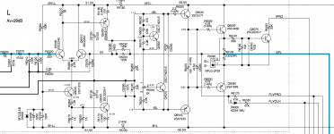
I would like to clarify about the biasing circuit used on this amp. I have done some research on Vbe multiplier circuits but most of the circuits I came across the variable resistor is connected to the base of the Vbe multiplier. However in this unit the VR is connected to another transistor’s base Q6010. I am finding it a bit hard to grasp how this works. Could someone kindly explain.
Q6010 is placed next to one of the drive transistor and it has got what looks like thermal compound applied to it. What is the reason for this?
If it was a biasing issue and some how it caused the output transistors to short out, note B-C-E were shorted - why didn’t it take out the drive transistors? The drive transistors still checks out ok.
All of the components related to the biasing part of the channel checks out ok but hypothetically speaking what component failure for e.g.: the potentiometer’s contacts loosing connection, some kind of thermal effect messing up with the biasing circuitry’s transistors?.
If its some kind of an issue which only causes the fault when power is applied what further troubleshooting should I be doing on this circuit? At the moment I am waiting for the replacement parts to arrive but meanwhile I would like to figure out what exactly caused the fault - could I power up the amp without the output transistors and see if the proper voltages are preset which is shown on the SM and lets say if the drive transistors are faulty, ‘leaky’ for instance would I be able to measure that?
Based on what I have detailed above, what’s your opinion for the reason for the fault to occur?
Thanks in advance for the help.
P.S - I couldn’t find replacement for some of the transistors and resistor so here are the equivalents that I have ordered
2SC1740S-S ——— 2SC2240
2SA1930 ——— A1837
0.22 Ohm 2W emitter resistors —— 0.22 Ohm 5W
Also note that there are some film capacitors which looks a bit black, I am not sure it was like it to start with. It measures ok especially when compared to a working circuit. Hope you can see it in the photo.
Attachments

If the wiper on R6040 lifts, the bias transistor opens up, and both driver and output transistors get slammed full on. This is a good way to destroy output transistors
I had a problem like this with a Sony receiver, and I went through a couple of sets of outputs before I realized what was going on. It was one of those cheap-a** phenolic wafer carbon trim pots. I replaced the bias pot with a proper sealed cermet pot, and I was able to keep output devices after that. If the pot is configured as a rheostat instead, the situation is far less traumatic if the wiper happens to open up. The bias increases somewhat, but at least the output devices don't get slammed on all the way.
I had a problem like this with a Sony receiver, and I went through a couple of sets of outputs before I realized what was going on. It was one of those cheap-a** phenolic wafer carbon trim pots. I replaced the bias pot with a proper sealed cermet pot, and I was able to keep output devices after that. If the pot is configured as a rheostat instead, the situation is far less traumatic if the wiper happens to open up. The bias increases somewhat, but at least the output devices don't get slammed on all the way.
Ah I see thanks, I did measure the resistance when the wiper is moved and the needle on my meter moved smoothly without any erratic movement. But yes a dirty contact is very much a possibility! considering that this unit is 6 years old and this is the first time it has been opened.If the wiper on R6040 lifts, the bias transistor opens up, and both driver and output transistors get slammed full on. This is a good way to destroy output transistors
I had a problem like this with a Sony receiver, and I went through a couple of sets of outputs before I realized what was going on. It was one of those cheap-a** phenolic wafer carbon trim pots. I replaced the bias pot with a proper sealed cermet pot, and I was able to keep output devices after that. If the pot is configured as a rheostat instead, the situation is far less traumatic if the wiper happens to open up. The bias increases somewhat, but at least the output devices don't get slammed on all the way.
With your experience were you monitoring the bias and noticed something peculiar happening as it was warming up? or was it pretty much instantaneous, were you able to play music through it for sometime? Also did it take out the drive stage as well?
Sorry for the noob question- but could you explain what you meant by 'configured as a rheostat'.
Thanks again
Last edited:
With the Sony I was fixing, the outputs blew as soon as I hit the power switch.
In your case, moving the pots around a bit with the power off (with maybe some contact cleaner to help) may be sufficient to give the unit a new lease on life, as long as you remember to re-tweak the bias after messing with the pots. Maybe figure out which way to turn to adjust the bias to a minimum, so there are no nasty surprises when you turn on the power again, then tweak the bias back up to spec. The pots in the Sony receiver I fixed were far sleazier than the ones I see in your pictures, though yours are still open construction, so there might be a chance for contamination.
In your case, moving the pots around a bit with the power off (with maybe some contact cleaner to help) may be sufficient to give the unit a new lease on life, as long as you remember to re-tweak the bias after messing with the pots. Maybe figure out which way to turn to adjust the bias to a minimum, so there are no nasty surprises when you turn on the power again, then tweak the bias back up to spec. The pots in the Sony receiver I fixed were far sleazier than the ones I see in your pictures, though yours are still open construction, so there might be a chance for contamination.
Strange circuit, its like a double Vbe multiplier.
As said previously wiper problems will blow outputs.
I would replace the bias pot for starters before doing any more powered up testing.
As said previously wiper problems will blow outputs.
I would replace the bias pot for starters before doing any more powered up testing.
Here's a picture showing the two potentiometer configurations, one fail-safe, one not. The fail-safe config has the disadvantage of the full divider current flowing through the wiper circuit, rather than just the transistor base current. This may possibly result in a little more noise in the bias circuit, though the cap that should be across the bias divider might squelch that.
Attachments
Bias range is determined by the current flowing through R6030, Vce-q6000, R6040 and R6050. The current through this branch is roughly Vbe-q6010 (0.7Vdc, temp compensation on heat-sink) / R6050 and part of R6040.
Vce-q6000 is the same trick with R6000 and R6010 and act as an (rubber) zener (1.22-1.3Vdc approx).
Wiper up to R6010: 1.982Vdc (+/- 0.991Vdc)
Wiper down to R6050: 2.444Vdc (+/- 1.222)
Bias spec is +/- 1.1Vdc (2.2Vdc total), just in range.
Q6000 prevents the bias regulator from opening to much.
Vce-q6000 is the same trick with R6000 and R6010 and act as an (rubber) zener (1.22-1.3Vdc approx).
Wiper up to R6010: 1.982Vdc (+/- 0.991Vdc)
Wiper down to R6050: 2.444Vdc (+/- 1.222)
Bias spec is +/- 1.1Vdc (2.2Vdc total), just in range.
Q6000 prevents the bias regulator from opening to much.
Attachments
Thanks everyone for the input, yes as suggested I would 'deoxit' the VR or possibly try to get a replacement.
So the capacitor C5050 is used to smooth noise in the bias circuitry right?
Thanks for the break-down of the bias circuitry. When you mentioned 'Vbe-q6000' did you mean Vbe minus Voltage drop across q6000? and also I am hearing the word 'rubber' for the first time in this context. I haven't read that before.
Please correct me if I am wrong, as a hypothetical situation - Q6010 becoming 'leaky' could potentially cause havoc compared to Q6000 right? I understand any amount of leakage is not good. I am getting 2SC2240 for replacement.
Some further questions I have are
Once again thanks very much for the help I really do appreciate it.
So the capacitor C5050 is used to smooth noise in the bias circuitry right?
Bias range is determined by the current flowing through R6030, Vce-q6000, R6040 and R6050. The current through this branch is roughly Vbe-q6010 (0.7Vdc, temp compensation on heat-sink) / R6050 and part of R6040.
Vce-q6000 is the same trick with R6000 and R6010 and act as an (rubber) zener (1.22-1.3Vdc approx).
Wiper up to R6010: 1.982Vdc (+/- 0.991Vdc)
Wiper down to R6050: 2.444Vdc (+/- 1.222)
Bias spec is +/- 1.1Vdc (2.2Vdc total), just in range.
Q6000 prevents the bias regulator from opening to much.
Thanks for the break-down of the bias circuitry. When you mentioned 'Vbe-q6000' did you mean Vbe minus Voltage drop across q6000? and also I am hearing the word 'rubber' for the first time in this context. I haven't read that before.
Please correct me if I am wrong, as a hypothetical situation - Q6010 becoming 'leaky' could potentially cause havoc compared to Q6000 right? I understand any amount of leakage is not good. I am getting 2SC2240 for replacement.
Some further questions I have are
- Why doesn't it take out the driver transistors like the output transistor? I haven't had much experience working on amps but from most of the stuff that I have read and seen the driver transistor seems to be intact even when the outputs short out, but everyone recommends to change them anyway.
- 'IPRO' is current protection, shouldn't this protection be engaged when there is a bias issue? There are other two protection signals but I'm not sure what it stands for 'FLVPRO' and 'FLVOLH' the service manual is not really descriptive on this.
- What is the purpose of Q5030 and Q5040? Its not related to the biasing right? Is it the VAS stage?
Once again thanks very much for the help I really do appreciate it.
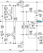
No, to pass the signal from the upside of the bias circuit to the downside, as Q6010 is not passing it through very well. They'd better used a topsy-turvy circuit with PNP's (instead of NPN's), as a common base circuit is made for that. When using NPN's, better have the signal coming in from the lower side.So the capacitor C5050 is used to smooth noise in the bias circuitry right?
An even better bias circuit is independend of this, but is more elaborate (only a little bit), and shows the lazyness or ignorance of this designer (following worn out design rules).
Vbe-q6000 is the base-emittor voltage drop, more or less some 0.7Vdc (not 'negative').Thanks for the break-down of the bias circuitry. When you mentioned 'Vbe-q6000' did you mean Vbe minus Voltage drop across q6000? and also I am hearing the word 'rubber' for the first time in this context. I haven't read that before.
The compound of Q6000, R6000 and R6010 is called a rubber zener (I found out lately - american slang), as the relation between R6000 and R6010 determines the Vce-q6000 (Vce = ((R6000+R6010)/R6010)*Vbe).
If Q6010 is really broken (fried - conductive - zero ohm), the bias is shut off.Please correct me if I am wrong, as a hypothetical situation - Q6010 becoming 'leaky' could potentially cause havoc compared to Q6000 right? I understand any amount of leakage is not good. I am getting 2SC2240 for replacement.
Actually, Q6010 is conducting most of the current from Q5030 to Q5040 with the desired and adjusted bias voltage. You may call the leaky, but in this case 'intended'.
If the driver can handle the current draw from a broken or shorted output bjt, it won't be taken out. But it can have had a serious 'current-hit', so better replace tbs.Some further questions I have are
Why doesn't it take out the driver transistors like the output transistor... but everyone recommends to change them anyway.
'IPRO' is current protection, shouldn't this protection be engaged when there is a bias issue? There are other two protection signals but I'm not sure what it stands for 'FLVPRO' and 'FLVOLH' the service manual is not really descriptive on this.
What is the purpose of Q5030 and Q5040? Its not related to the biasing right? Is it the VAS stage?
Ipro is active when to much current is flowing through Q6030 or Q6040 (depends on specs and circuit). Here Q6070 trips when the voltage over P6080 exceeds ( (56k+10k)/10k*0.6 =) some 4Vdc -> ~ 4/(0.22)=18A (single side trip).
FLVPRO is zero dc-voltage detect (offset), FLVOLH seems over voltage to me, positive side only (lazyness again).
Q5030 is the main amplifying bjt (must be a very good one), Q5040 its load being a current source. Their dc-current is needed for the bias.
Last edited:
Better know it than to guess it. Next: enjoy your favourite music (here: Tombeau de Couperin by Ravel while depuzzling the various colours of the 2SK30A supported by a Pinot Noir d'Alsace).
Wise words 🙂Better know it than to guess it. Next: enjoy your favourite music (here: Tombeau de Couperin by Ravel while depuzzling the various colours of the 2SK30A supported by a Pinot Noir d'Alsace).
Thanks everyone for the help.
I'd like to add one more point for completion sake, when I was first testing out the amplifier on my bench after installing the borrowed transistors and resistor from the unused channel I heard a relay click while I was playing music, nothing ill happened the amp was working fine. I turned off the amp and back on again was playing music and after couple of seconds I heard the relay click. I didn't figure out what it was. Its not the speaker relay which clicks when the amp is first turned on. What could this be?
I'd like to add one more point for completion sake, when I was first testing out the amplifier on my bench after installing the borrowed transistors and resistor from the unused channel I heard a relay click while I was playing music, nothing ill happened the amp was working fine. I turned off the amp and back on again was playing music and after couple of seconds I heard the relay click. I didn't figure out what it was. Its not the speaker relay which clicks when the amp is first turned on. What could this be?
- Home
- Amplifiers
- Solid State
- Help understand biasing circuit, possible culprit for output shorting?