Hello, I would like to test this config (see R17 to cathode resistor, instead of to ground)
I notice on .op simulation that the tube is biased much hotter, the frequency response is better on the bass and that reduces the load of the driver stage.
But I don't know which could be the real pros and cons of bootstrapping, if you can enlight me. as I don't see schematics with this config.
Thanks
I notice on .op simulation that the tube is biased much hotter, the frequency response is better on the bass and that reduces the load of the driver stage.
But I don't know which could be the real pros and cons of bootstrapping, if you can enlight me.
as I don't see schematics with this config.Thanks
Attachments
You get nearly the same bias current as with a halved cathode resistor, but you have more local series feedback.
You did not show the complete schematic.
The two Un-bypassed 1000 Ohm cathode resistors means the gain is very low.
And it also means the plate resistance is very high, even with the UL connection on the screen.
Are you sure there is not a bypass cap beyond where the schematic is cut off at the right side?
I am just asking for a more complete schematic, to give a more sure analysis.
And . . . the driver has to drive the 470k resistor, R1. So even if the bootstrapping of R17 is 100%, the driver only sees 470k
instead of 470k/2 = 235k if there was no bootstrap effect (if the cathode resistors had a bypass cap).
One more thing, the point of a grid stopper resistor is to provide a super short wire at the tube socket grid post, that goes to the grid stopper resistor, and does not go to anything else.
Your schematic shows the leads of both R9 and R17 going to that socket grid post.
Depending on the exact way you wire both resistors, it can defeat the purpose of the grid stopper resistor.
Schematics that show it that way are many. But they all have something in common, those schematics do not show the true principal method of connecting a grid stopper resistor.
Last edited:
I think having the grid at a positive voltage means for the same bias current the cathode is at a more positive voltage. So that means higher cathode resistors and more wasted power dissipation.
And . . . the driver has to drive the 470k resistor, R1. So even if the bootstrapping of R17 is 100%, the driver only sees 470k
instead of 470k/2 = 235k if there was no bootstrap effect (if the cathode resistors had a bypass cap).
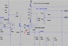
Hi, yes, of course there is a cathod cap on the right. Grid stopper resistor is soldered on the KT66 pin.
Why the driver only sees 470k and not 235k ?
Last edited:
I think having the grid at a positive voltage means for the same bias current the cathode is at a more positive voltage. So that means higher cathode resistors and more wasted power dissipation.
Can this be seen as a sort of fixed bias?
You get nearly the same bias current as with a halved cathode resistor, but you have more local series feedback.
I wrote this not knowing that the cathode resistor is decoupled. Knowing that, I can't think of any advantage over just halving the cathode resistor.
Can this be seen as a sort of fixed bias?
No, because the grid-cathode voltage is still proportional to the average cathode current.
Can this method be used to increase the driver output impedance exceeding the grid leak resistance limit for power tubes, and thus increasing a bit the driver gain?
If 6A3sUMMER is correct, and I put 1MEG (instead of 470K) for both R1 & R17 resistors, am I still within the KT66 limit (470k), with the driver seen 1Meg?
If 6A3sUMMER is correct, and I put 1MEG (instead of 470K) for both R1 & R17 resistors, am I still within the KT66 limit (470k), with the driver seen 1Meg?
I don't see the point in this idea. If the KT66 cathode resistors are capacitively decoupled, there ain't no bootstrapping at all. Hence the effectively paralleled grid leak resistors present a heavier load to the driver tube that decreases it's gain.
Best regards!
Best regards!
ygg-it,
How about the complete schematic?
Without that, we can not determine the rp of the driver tubes.
And, the schematic is in-correctly marked Pentode Mode,
But it is actually drawn as Ultra Linear Mode.
Where did you get this schematic?
Is the 470k R17 Rg connected to the output tube g1 directly, or is it connected to the left side of the grid stopper resistor (R1)?
And, you said there is a bypass cap across the output tube cathode resistors, so there is no bootstrap effect on R17, the 470k Rg.
Because we can not see the complete driver circuit, we can only guess at the rp of those triodes.
And how much extra gain are you planning to get from a parallel triode driver with rp/2 = 30k, in parallel with 150k in series with 15k (165k).
The 30k rp/2 in parallel with the 165k = 25k.
Changing the two 470k resistors to 1meg each, will not give even 1dB more gain from the driver.
Last edited:
- Home
- Amplifiers
- Tubes / Valves
- S.E. bootstrapping: pros and cons