Hello all,
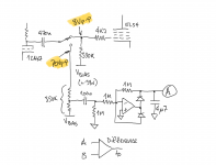
I'm new here and have a noob question. Maybe you can help. I have built a prototype for a valve amp using EL34s and cathode-coupled splitter. It works quite well. I have a potentiometer to adjust the gains of the splitter to balance them. So, I get this idea that I could build a small microcontroller circuit to allow me to monitor the balance all inside the amp. (See the attached schematic.)
The way it works is to switch the outputs of the splitter from the output tube grids to my measurement circuit while switching the amp input to a generated test signal. The circuit uses a precision rectifier in each phase and a difference amp to drive the ADC of a microcontroller and to display the difference on a small display. The point of switching out the output tubes is to eliminate the need for a (relay-switched) dummy load.
As shown in the schematic, the circuit works just fine. Except, as I indicated, when driving the grids the voltage swing from the splitter is way smaller than when driving the measurement circuit.
Is the grid load really that big? I must be overlooking something. Or maybe this just isn't a workable idea.
Just for completeness, I should mention that the static (bias) voltages measure the same at both the "grid" resistor and the "measure" resistor. I am using 10x (10Meg) probes.
Any help in understanding what's going on here would be really appreciated. Even if the bottom-line is that I'm being something of an idiot.
Thank you if read this and thanks in advance for any feedback.
Attachments
Doh! See, I'm an idiot. Yes, there's NFB. That explains it.
Thank you!
I'm more of a programmer than a hardware sort. That's why I think adding software to everything like this self-contained measurement. So, what do you think. Is it still valid to do this even though the "without NFB" levels are higher? Is the measurement still valid even if the output tubes are out-of-circuit?
BTW, this all started because I have cathode resistors (10Ohm) to measure the output tube currents. The microcontroller ADC also allows internal measurement of that and that works just fine.
There should be a way to have the monitoring circuit permanently connected, with no need
to switch it in or out. There's already a coupling capacitor at the input of the monitoring circuit.
You don't want to alter the amplifier's circuit during the monitoring, that will alter the balance
that you are trying to monitor.
to switch it in or out. There's already a coupling capacitor at the input of the monitoring circuit.
You don't want to alter the amplifier's circuit during the monitoring, that will alter the balance
that you are trying to monitor.
Last edited:
Rayma, what you say makes total sense and I only went down the path described in order to avoid having to switch in a dummy load when making the measurement. A kilohertz coming out of the speakers at ten watts is not pleasant. But for the balance to be really representative that's likely what I'll have to do. After all, it's just putting an already necessary relay in a different location and adding a big resistor.
Thank you for your responses!
Thank you for your responses!
The grid is capacitive so will load with a capacitance that depends on size of tube.
Its usually in the datasheet for the valve.
Its usually in the datasheet for the valve.
...adjust the gains of the splitter to balance them. So, I get this idea that I could build a small microcontroller circuit ...
This is much too clever. I've had two amps with manual trims and once set they never needed attention, even after tube change.
Also the following grid load DOES matter, even if only a little bit. What if your 390k grid resistor drifts to 330k or 420k? If you disconnect it you are not measuring it.
And as said all gain relations are skewed under NFB. If you code a self-driving car, which self-corrects from camera to steering wheel, and you disconnect the steering to do calibration, it's gonna run wild.
A cathodyne is locked to resistor values (tube hardly matters). Use OVER-rated <2% resistors and be done with it.
If your microcontroller needs a job, let it monitor cathode currents and send you a text if any of them are drifting away from usual values. (In a big fussy radio station, that was a half-time job for the junior engineer.)
PRR, yeah, you're right. I even noticed this myself now that you mention it. I switched the splitter tube from a ECC83 to a 6N2P and the levels were the same. That should have sunk in but didn't. Thanks for the reality check.
I got the impression from post # 1 that the phase splitter is a long-tailed pair (cathode coupled). But once adjusted, probably that one will stay stable also.
PCL200, you're correct, the splitter is a long-tailed pair/cathode-coupled type. I hadn't noticed PRR's reference to a cathodyne (I know that as a concertina). As I mentioned, when I did change tubes, the levels in the two phase outputs were still equal (or nearly so) as indicated by my circuit. Maybe just luck? Or are long-tailed pairs also fairly indifferent to the actual tube once adjusted?
I think the tube used in a long-tail does matter to some degree. In a cathodyne the tube doesn't amplify (gain is allmost 1) because of the inherent high (100%) feedback. In a long tail pair there is still amplification going on (for an ECC83 the gain is about 25) so differences in tubes can matter. GNFB does compensate these differences but I think that it is better to start with as good as possible balance before applying GNFB (else GNFB could make every amplifier work perfectly).
I think that once the balance is set, it will not change much (unless the tube gets duff unevenly between the sections), but this statement is just based on what I think + some experience, so please don't take it as 'the' truth.
Probably other forum members know more about this aspect than me.
I think that once the balance is set, it will not change much (unless the tube gets duff unevenly between the sections), but this statement is just based on what I think + some experience, so please don't take it as 'the' truth.
Probably other forum members know more about this aspect than me.
Last edited:
If the tail impedance in a LTP is high enough (a CCS could be considered) and both plate impedances are perfectly equal, perfectly balanced output signals could be achieved even with very dissimilar tubes, say a 12AU7 and a 6922 triode. This has been shown here years ago and is easily to comprehend.
I see a drawback in a CCS as a LTP's tail, though: The tail impedance is mainly defined by the parasitic capacitances, hence highly frequency dependant.
Best regards!
I see a drawback in a CCS as a LTP's tail, though: The tail impedance is mainly defined by the parasitic capacitances, hence highly frequency dependant.
Best regards!
Thanks for your thoughts. Some background to my posted circuit. At some point, the voltages to the splitter have to be adjusted for equal signal levels. I just assumed that changing the tube would alter that and wanted a way to monitor that without hooking up test equipment. The complexity came from my completely unnecessary requirement that the direction of the level mis-match, i.e., which triode was lower or higher, could be indicated. (So, I could indicate which way to turn the pot. Yeah, I'm that crazy, sometimes.)
Thanks again to you all.
Thanks again to you all.
Last edited:
> are long-tailed pairs also fairly indifferent to the actual tube
Follow the current. In LTP or in concertina, where can the current go? Through the tube AND the load resistors; none should be leaking out the grid. As Kay says, a high-Z tail (the tail is a signal current "leak") makes balance look better; that may not sound better.
Follow the current. In LTP or in concertina, where can the current go? Through the tube AND the load resistors; none should be leaking out the grid. As Kay says, a high-Z tail (the tail is a signal current "leak") makes balance look better; that may not sound better.
PRR, you say "follow the current". I had a thought today and made a few measurements. I have 10 Ohm resistors (well-matched) from the cathodes to ground for the output tubes. (So the current can be monitored.) It occurred to me that there must be some signal impressed on these resistors. Turns out to be a few tens of millivolts of signal under light load. A quick test showed that tuning the sum of the two (0° and 180°) to minimum also resulted in balanced levels from the splitter...which I kind of expected.
Is that to be expected? Could it be that a good balance there is a better indicator than the actual splitter outoput levels?
I guess I'm doing this in order to learn more about circuits and how to measure them. Good and fun.
Thanks
Is that to be expected? Could it be that a good balance there is a better indicator than the actual splitter outoput levels?
I guess I'm doing this in order to learn more about circuits and how to measure them. Good and fun.
Thanks
- Home
- Amplifiers
- Tubes / Valves
- How does the output grid load the driver?